The OPA is better regarding noise than the 4562, so use it if you have one available.Damn, was hoping to do some OPA211 smd soldering but if you say 4562 is better then i'll do that. I think i'll probably do 100x and 10x options jumper selectable. So since 4562 is dual, i'll use one for amplifier and other one i'll just ground it.
I got some thin copper sheets that i can probably use to shield this LNA.
Btw i don't even need to say that socket for 4562 is out of the question,right?
Gain selection is nice feature, but with very low level amplifiers you have to be careful when you add switchings, etc. All needs to be low-impedance, carefully shielded (but it is possible)
Yes, real oscillations occur at 80 ohm, but any value reduces the stability margin, even if it does not cause direct oscillations so it is preferable to eliminate it completely for the 337Ok, thanks LV.
I'll remove the ones with the LM337.
You say : "The 337 does not tolerate resistance at all." , but after removing the ceramic cap , everything seems ok . could the 33 be the cause of the instability with the ceramic cap ?
No problem, other members will certainly find additional application examples useful and inspiring@Elvee if you think this is a bit offtopic i'll stop here with this modified denoiser versions. I just wanted to show that we are all grateful that you got this idea so we we're playing around it to see if we can improve it a bit as stand alone PSU.
Uploaded several PSRR curves for different regulators, the Denoiser and Nonoiser being two of them.
If you can take a look and tell me if anyone got similar or different results.
Looking for a good power supply for a RIAA preamp
If you can take a look and tell me if anyone got similar or different results.
Looking for a good power supply for a RIAA preamp
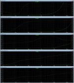
Simulated impedance competition.
I took the most remarkable impedance curve regulators, and put them one over the other too see how they compare.
Also added an LT3042 that I have been working with and I think also belongs on the "superregulator club".
Limits were set for bandwidth, 1Hz to 220KHz, and 40 miliohms was the vertical limit, which seems reasonable.
The Nonoiser was the best performer.
We can go further in the lower scale, but I wonder if that is necessary at such low results in practical terms.
Same thing goes for the PSRR comparison I made on the other thread.
To my surprise, at least for some of the simulations, the CRC filter turned in better results than using a pre-regulator. Can someone explain that to me?
Attachments
You could also add the 12 discrete reg.Also added an LT3042 that I have been working with and I think also belongs on the "superregulator club".
Not the highest performer, but relatively simple and cheap
If you use a log scale, this will make the comparison easierLimits were set for bandwidth, 1Hz to 220KHz, and 40 miliohms was the vertical limit, which seems reasonable.
The Nonoiser was the best performer.
We can go further in the lower scale, but I wonder if that is necessary at such low results in practical terms.
There is no theoretical limit to what a passive LPF can achieve at high frequencies.To my surprise, at least for some of the simulations, the CRC filter turned in better results than using a pre-regulator. Can someone explain that to me?
Regulators have various mechanisms limiting their performance, but in general they are flatter than passive filters.
You could also add the 12 discrete reg.
Not the highest performer, but relatively simple and cheap
OK, I will add it.
If you use a log scale, this will make the comparison easier
But the curves will have a different shape. I was trying to use the same parameters WJ had used on his measurements.
There is no theoretical limit to what a passive LPF can achieve at high frequencies.
Regulators have various mechanisms limiting their performance, but in general they are flatter than passive filters.
Maybe it's my implementation. What I did was add a regulator before an LT3042, which had an excellent PSRR response. The results with the pre-reg were awfully poor.
In any case I was surprised that at the simulation results of the LT3042 in impedance and PSRR. Pity it's SMD.
As I have a few "violet" LT3042 regs I had bought in eBay, I was thinking of adding the CRC before the pcb and see what happens. That is for the moment when I make the actual comparisons with the real boards.
You could also add the 12 discrete reg.
Not the highest performer, but relatively simple and cheap
You mean which regulator? The one you helped me get to for the power amp, with two transistors, or the original Luxman supply?
Pity it's SMD.
No , SMD's are OK , in packages like D2PAK TO-263 , TO-261, TO-223, TO-252, ...
But when those <curse> manufactors , <curse again>, put it in those <curse> 3 mm packages with 10 leads , it is NOT ok.

Here are the simulated plots:
The denoiser in its latest version:
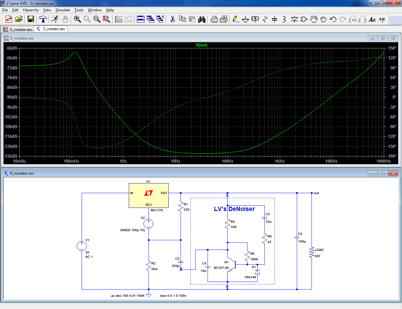
Here is the sim from Jack, with another simulator:
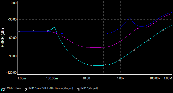
The nonoiser:
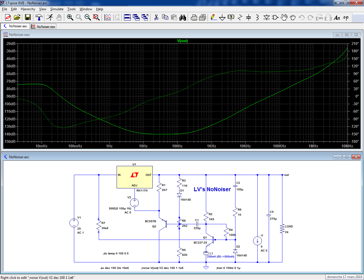
The sims are a bit optimistic compared to the reality as always, but you can expect >100dB rejection at 100Hz for the denoiser and 125dB for the nonoiser without the ripple compensating resistor.
With the resistor (that needs to be individually adjusted) you can gain an additional ~10dB at 100Hz
The denoiser in its latest version:
Here is the sim from Jack, with another simulator:
The nonoiser:
The sims are a bit optimistic compared to the reality as always, but you can expect >100dB rejection at 100Hz for the denoiser and 125dB for the nonoiser without the ripple compensating resistor.
With the resistor (that needs to be individually adjusted) you can gain an additional ~10dB at 100Hz
Attachments
First of all, I know there's way, which I can't remember, where you load data so LTSpice can draw several curves so you compare them immediately.
One big improvement I noticed on all PSRR simulations was adding a CRC filter before the regulator, visible on the low frequency region and the lower range it could reach for the flat line. The question is whether it's worth, money wise and audio quality wise, to use that CRC. Comments are welcome.
Another question is which are which is the most useful, for audio matters, horizontal bandwidth. Isn't it better to start in say 1Hz on the left and 100KHz or 220KHz on the right? The latter is already used on above graphs.
It depends on what you want to do: if you need to see the effect of a component or parameter change, the .step command is the simplest way.First of all, I know there's way, which I can't remember, where you load data so LTSpice can draw several curves so you compare them immediately.
If you want to compare completely different circuits, there is certainly a way to use the .raw files of the different sims, but i never used or explored that possibility.
The most straightforward method is probably to put all the circuits you want to compare on single schematic, and plot the various nodes in the same graphic.
That's not very clear: the effect of a passive LPF will always be to improve the rejection at higher frequencies.One big improvement I noticed on all PSRR simulations was adding a CRC filter before the regulator, visible on the low frequency region and the lower range it could reach for the flat line. The question is whether it's worth, money wise and audio quality wise, to use that CRC. Comments are welcome.
The low frequency effect will depend on how much you are ready to spend on the capacitors, and how much voltage you are ready to lose in the resistor.
In addition, the RC filter will degrade the static load regulation, because the input voltage will change with the load
You are completely free to use whatever limits you want: you can limit yourself to the strict audio bandwidth, 20Hz-20kHz, but having a wider view gives a better perspective.Another question is which are which is the most useful, for audio matters, horizontal bandwidth. Isn't it better to start in say 1Hz on the left and 100KHz or 220KHz on the right? The latter is already used on above graphs.
How much wider depends on your tastes and what you want to examine, there is no fixed rule.
That's not very clear: the effect of a passive LPF will always be to improve the rejection at higher frequencies.
The low frequency effect will depend on how much you are ready to spend on the capacitors, and how much voltage you are ready to lose in the resistor.
In addition, the RC filter will degrade the static load regulation, because the input voltage will change with the load
What about a CLC filter then? Not too familiar with inductors for Pi Filters.
With 3.3mH the falling curve is quite nice.
Though inductors are large for this application, aren't they?
They are more effective, and waste less voltageWhat about a CLC filter then? Not too familiar with inductors for Pi Filters.
Not necessarilyThough inductors are large for this application, aren't they?
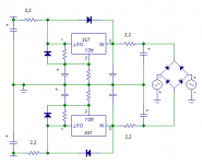
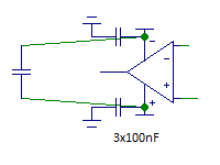
That's a bad example: it is a CMC, it won't work.
This would be better:
RLB0812-332KL Bourns | Mouser Canada
Preferably chose a model having sufficient losses, to avoid resonance effects with the caps
You say the CMC choke it won't work between capacitors or that it won't work at all?
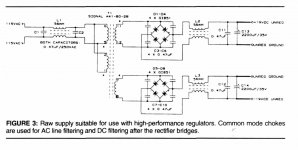
This the supply suggested and used by Gary Galo for his raw supplies, following tests done by Rick Miller for The Audio Amateur.
They were later used as raw supplies for Gary Galo's superregulators.
As you can see, the 56mH CMC chokes were used before the transformer and after the diode bridge. Not between capacitors.
Those Panasonic types are not available anymore, but there other brands.
I didn't find any models for either the inductors you suggested or those CMC.
Attachments
Why not? It's 1.1A, 3.3mH.That [7448640398 Wurth Elektronik | Mouser Canada] 's a bad example: it is a CMC, it won't work.
But it only handles 60mA!This would be better:
RLB0812-332KL Bourns | Mouser Canada
- Home
- Amplifiers
- Power Supplies
- D-Noizator: a magic active noise canceller to retrofit & upgrade any 317-based V.Reg.