Thanks, now is more clear, but what is R8(2K2) in non noiser circuit?I agree: the project started with the denoiser, and the nonoiser grafted itself to the thread, which didn't contribute to clarity.
Here is an updated denoiser schematic, including the polarities of capacitors
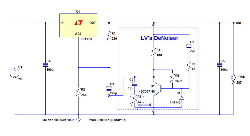
The voltages of the capacitors have to match the output voltage (and input in the case of C4, which is optional: in principle, it should already be there).
The calculation of the output voltage is just like an ordinary 317 reg: use R1 and R2 in the formula provided in the datasheet (for 24V, R2 would need to be 4K1).
For the nonoiser, the adapted schematic is here:
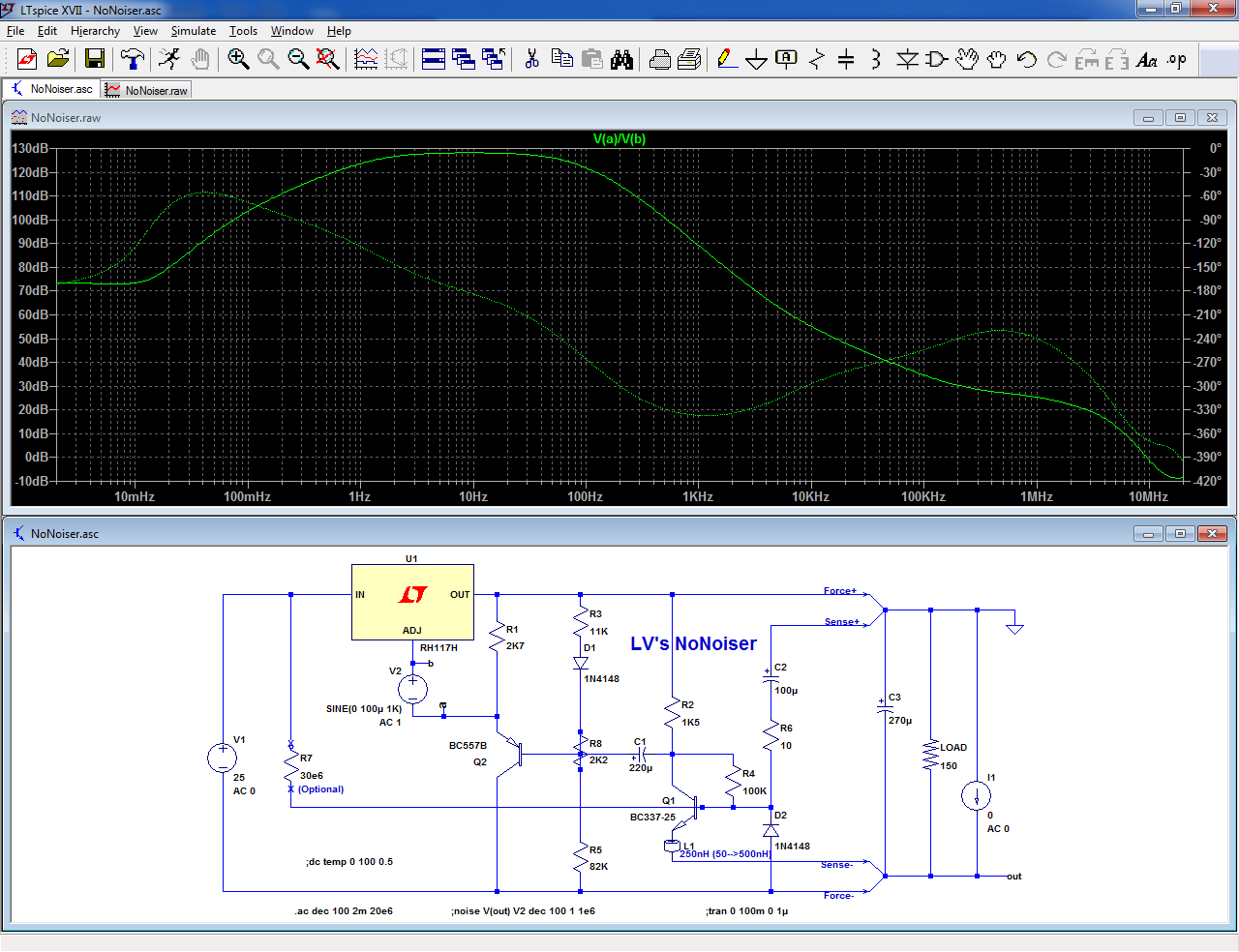
The base formula is no longer usable, but I provided exact and approximate alternatives here:
D-Noizator: a magic active noise canceller to retrofit & upgrade any 317-based V.Reg.
Is it a variable resistor?
R3 can improve stability, when the 317 implementation is non-standard, or if you want to try other types of regulators.
It also makes the circuit more forgiving of layout blunders.
It is unnecessary when used with a plain-vanilla 317 circuit (but it will do no harm)
So , like if someone changed the resistor values higher for lower quiescent current ...
")
What are the worse layout blunders you can make with a simple cicuit like the DeNoiser ?
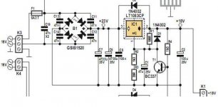
Here's a recent ,well 2010 , Elector circuit . Notice the 47nF over the diodes. Can 10n to 47 nF hurt much even if you don't need them ?
(I don't know how diyaudio regards copy rights with posting stuff from Elektor)
Attachments
It is a trimpot. I drew it that way, to keep the drawing functional in sim.Thanks, now is more clear, but what is R8(2K2) in non noiser circuit?
Is it a variable resistor?
If you don't need adjustment, simply short k-D1, b-Q2 and R5 (that's the configuration used by the sim)
I have no precise idea, but I rely on the creativity of would-be builders to find very good ones.So , like if someone changed the resistor values higher for lower quiescent current ...
What are the worse layout blunders you can make with a simple cicuit like the DeNoiser ?
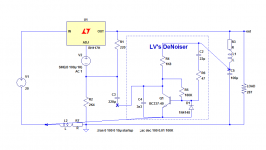
Here is a possible example, with the wiring parasitics shown explicitly.
That will create parasitic poles, and accidents in the correction curve.
Here's a recent ,well 2010 , Elector circuit . Notice the 47nF over the diodes. Can 10n to 47 nF hurt much even if you don't need them ?
They are probably going to do no harm: they might cause some relatively low frequency ringing on the AC side, but in principle it should be innocuous.
On the plus side, they will ensure a HF continuity between the DC and AC sides, which is desirable to avoid modulation effects from the rectifier diodes, but a value lower than 47nF will be as effective, and will result in a higher damping.
One could discuss the merits of a better damping vs. higher ringing frequency, but if you feel it's a concern, you can opt for Mark's bell-ringer solution.
Anyway, keeping ~4.7nF directly across each diode is advisable, to eliminate PIN-diode and similar effects: it will help eliminate buzzing in nearby radio receivers
Attachments
The circuit is designed for highish Hfe transistors, like the BC337-40 or the ZTX.
However, because of the (feedback) mode of bias, and the fact that the correction amplifier should only operate on a small dynamic range*, practically any gain range will always work with any bias resistor (within reason, of course).
What is going to change is the performance: I have used a collector resistor as large as possible, whilst keeping the collector current as large as possible, to maximise the transconductance and the voltage gain.
Since these objectives are somewhat contradictory, the C-E voltage is kept to the minimum practical to remain in the fully linear range, and accept normal component deviations.
If you go outside the normal deviation, the circuit will continue to function, but with a penalty of perhaps 2~3dB, depending on the values.
Hey LV ,
What is the optimal C-E voltage for the DeNoiser ?
In your original design , I measured about 4,55 V (at 15 V output and a BC817-25) .
I made a lower quiescent current one , with 3k6 going to the collector , kept the 180k to the base , but the C-E dropped to 3,00V . Then I put 270k to the base which brought it up to 3,97V . I could up it more like a 360-390k or even 470k to get it closer to your 4,55V.
The C-E voltage doesn't change with the load . So what is the ideal C-E voltage , and when/how does the noise of these high ohms resistors come in play ?
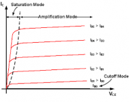
For a "normal" use, the lowest possible while remaining in the linear regime (out of the quasi-saturation region): on the right of the dotted line in this graph:What is the optimal C-E voltage for the DeNoiser ?
This will maximize the collector load and the voltage gain.
Numerically, this means >2*Vbe.
What is a normal use?
As a regulator for sensitive, low noise circuits.
If the load generates a strong, HF modulation current like a class B amplifier used to drive a HF magnetic loop, the correction transistor will need more C-E room to cope with the dynamic range, but that is normally exceptional.
That's perfectly OK, and increasing the collector resistor would only give very marginal improvements.In your original design , I measured about 4,55 V (at 15 V output and a BC817-25) .
In principle, they have no effect on the noise because the gain provided by the transistor and the low impedance of the regulator output makes them irrelevant.. So what is the ideal C-E voltage , and when/how does the noise of these high ohms resistors come in play ?
An exception could be the collector resistor, if you use a type (like carbon-composition) having a very large excess noise, but with all other types (including carbon-film), it is a non-problem
Attachments
Last edited:
Thick film SMD's may be better than carbcomp's on noise and voltage coefficient, but only by a slim margin....
Anyway, the beneficial effect of the denoiser is normally going to overcome that, and unless you use a granule microphone as a collector load, you are going to see an improvement.
One more thing worth mentioning: you asked about the noise effect of higher value resistors, and the answer I gave is perfectly valid.
However, using higher resistors normally means lower current levels (which of course is why you opted for them in the first place), and this means higher global noise levels.
I do not have quite in mind the exact formula for the noise vs. bias current for a forward-biased junction (B-E for example), but there is such a dependence: could be the square root, or any other power, but it definitely has an effect.
Another effect to consider is the noise current in the Adj. pin of the 317: it will remain the same whatever the impedance level around it is, and this will increase the level of noise to correct.
Since a limitation of the denoiser is precisely the amount of loop gain it can provide to eliminate the noise (which is why the nonoiser is more effective), it will probably have an effect.
I cannot tell exactly how much, because it depends on a lot of factors, but I can try to make a noise simulation to have a rough idea.
By comparison, the effect of having 3V instead of 4.55V for Vce is going to be absolutely minuscule....
Thick film SMD's may be better than carbcomp's on noise and voltage coefficient, but only by a slim margin....
Metalfilm resistors (the 50ppm/ºC) or thick film (100ppm-200ppm/ºC) , all use NiChr, so there won't be that much difference in noise.
The low current version is slower to stabilize to it's end voltage and I think the top voltage at start is a bit lower , but that may be to hard to be certain with just a DVM. Your DN after 23 sec , the low current one about 35 sec.https://duckduckgo.com/?q=stabilize
I am not too confident about that: even if the resistive materials are chemically identical (to be verified), the behavior of a film deposited by evaporation is probably very different from a dispersion in an ink.Metalfilm resistors (the 50ppm/ºC) or thick film (100ppm-200ppm/ºC) , all use NiChr, so there won't be that much difference in noise.
You could ask the question on the "Parts" section, some people may have more detailed information.
I tried to simulate the effect of a current decrease on the noise, but it is worthless, because the most important factor, the 317's noise is not modeled in the RH117: its noise voltage and current are zero
My breadboard setup is still more or less operational, so I will make the ultimate simulation test: reality.
I shall compare the regular denoiser with a randomly chosen BC337-25, and the LoPo variant in exactly the same conditions, except for the resistors values.
This should settle the issue regarding the impedance level.
The resistors quality is something different: if I find suitable carbcomp in my stock, I shall also test them.
Somehow I managed to miss this thread before. Very neat, I must say. If in doubt, I'd rather be using an LM317, a BC337 and a few passives than some exotic specialty part (which have a habit of becoming unobtainium eventually). Not like any sanely-designed circuit should actually require regulator performance like that, but hey - at least the power won't be the bottleneck. The only thing I don't like is the overshoot, probably a result of the two poles (related to the two coupling caps) being too close together.
I have to wonder whether you couldn't upgrade a (Darlington or MOSFET) cap multiplier to "super" level with a DeNoiser. I don't see why not. The result would appear to be looking an awful lot like a basic voltage regulator, just all AC-coupled, and presumably perform similarly as well. Sometimes you just want a clean supply, but don't care what it is within certain limits (a zener can be included to avoid overvoltage).
I have to wonder whether you couldn't upgrade a (Darlington or MOSFET) cap multiplier to "super" level with a DeNoiser. I don't see why not. The result would appear to be looking an awful lot like a basic voltage regulator, just all AC-coupled, and presumably perform similarly as well. Sometimes you just want a clean supply, but don't care what it is within certain limits (a zener can be included to avoid overvoltage).
I have rebuilt the setup and made the comparison: with the "regular" resistor values, I arrived at 0.55µV total noise (10Hz-10kHz); IIRC, it is a bit higher than the previous results, but the transistor is different, it is a BC337-25, and and I didn't take the utmost care in the grounding scheme, etc., and it is a breadboard.
I then increased all the resistors by a factor 5: 1K8-->9K1, etc. except for the input protection resistor.
I left all the caps identical.
To my surprise, the degradation was barely noticeable: the noise reached 0.6µV.
So, reducing quiescent current by a factor 5 has ~no impact on noise performance.
The DC stability is certainly going to be affected though.
I then made a further test: I used carbcomp resistors for the two most critical ones: the collector load and the Out to Adj resistor.
There again, no significant change.
To make the correction as wide as possible, I used what I estimated as the largest reasonable coupling cap in the collector: 220µF, and the base cap was a tradeoff: for an extended subsonic response, it needs to be high enough, but the pole becomes close to the other one, resulting in some humping.
It could be made smaller, if VLF is not very important, or the 220µF can be made larger.
The nonoiser has more favorable impedance levels, and does not show this behavior (which is entirely avoidable if necessary).
The limitations of "simple" cap multipliers stem from the Early effect of the pass transistor, which limits rejection to ~60dB or thereabout.
With the denoiser, you could certainly add another 35dB, probably more because you have more leeway in the choice of impedances compared to a 317.
It is also possible to stay open-loop, and compensate the Early effect, but that's another story
I then increased all the resistors by a factor 5: 1K8-->9K1, etc. except for the input protection resistor.
I left all the caps identical.
To my surprise, the degradation was barely noticeable: the noise reached 0.6µV.
So, reducing quiescent current by a factor 5 has ~no impact on noise performance.
The DC stability is certainly going to be affected though.
I then made a further test: I used carbcomp resistors for the two most critical ones: the collector load and the Out to Adj resistor.
There again, no significant change.
Yes.The only thing I don't like is the overshoot, probably a result of the two poles (related to the two coupling caps) being too close together.
To make the correction as wide as possible, I used what I estimated as the largest reasonable coupling cap in the collector: 220µF, and the base cap was a tradeoff: for an extended subsonic response, it needs to be high enough, but the pole becomes close to the other one, resulting in some humping.
It could be made smaller, if VLF is not very important, or the 220µF can be made larger.
The nonoiser has more favorable impedance levels, and does not show this behavior (which is entirely avoidable if necessary).
It would certainly be possible.I have to wonder whether you couldn't upgrade a (Darlington or MOSFET) cap multiplier to "super" level with a DeNoiser.
The limitations of "simple" cap multipliers stem from the Early effect of the pass transistor, which limits rejection to ~60dB or thereabout.
With the denoiser, you could certainly add another 35dB, probably more because you have more leeway in the choice of impedances compared to a 317.
It is also possible to stay open-loop, and compensate the Early effect, but that's another story
I then increased all the resistors by a factor 5: 1K8-->9K1, etc. except for the input protection resistor.
That's radical , a factor 5 , but good to know that 2 or 3 times as much , like I want, will do no harm. With 9k1 , did you measure the Vce with ... 5 x 180k = about a 1M base resistor ? Did you keep the 47 ohm resistor the same or also x5 ?
What is the input protection resistor ?
Did you mean also the LM317 bias setting R times 5 ? So going from the 220 ohm to 1k2 over the 1,252 V ref ?
I just did tests with an 1k8 resistor there (but without the DeNoiser) , to test a low quiescent current regulator for a logic IC circuit , and it still works , but without load the output voltage is a few 10's mV higher. I seems 1k2 is the highest you can go to keep it safe with low current loads as not-doing-anything CMOS logic IC's.
As the collector resistor was also scaled in the same proportion, there is no significant change, except those due to variations in Hfe; and as I said, the exact Vce is unimportant.did you measure the Vce with ... 5 x 180k = about a 1M base resistor ?
The 47 ohm is the protection resistor, and I kept itDid you keep the 47 ohm resistor the same or also x5 ?
What is the input protection resistor ?
Yes, everythingDid you mean also the LM317 bias setting R times 5 ? So going from the 220 ohm to 1k2 over the 1,252 V ref ?
All my tests were made with a 287 ohm loadI just did tests with an 1k8 resistor there (but without the DeNoiser) , to test a low quiescent current regulator for a logic IC circuit , and it still works , but without load the output voltage is a few 10's mV higher. I seems 1k2 is the highest you can go to keep it safe with low current loads as not-doing-anything CMOS logic IC's.
Here it is:I have to wonder whether you couldn't upgrade a (Darlington or MOSFET) cap multiplier to "super" level with a DeNoiser. I don't see why not.
Improving capacitance multipliers
As expected, the improvement over the plain vanilla version is ~30dB
Can DeNoiser be used together with the pre-regulator concept?
Where the first LT stabilizes the dropout between input and output of the second LT chip?
Would such DeNoiser Circuit be appended at the back of the preregulator,
or would it make sense to use two DeNoisers, as an integral follow-on module for each of the two LT chips?
...
What do you think, would the DeNoiser better the solution presented as the last picture on this webpage (boasting 100dB, or something?)
Using 3-pin regulators off-piste: part 4
It could, but it depends on what you want to achieve.Can DeNoiser be used together with the pre-regulator concept?
A prereg (without denoiser) will double the PSRR, but the output noise will remain the same.
Thus, the logical place to place a denoiser is at the last regulator.Would such DeNoiser Circuit be appended at the back of the preregulator,
or would it make sense to use two DeNoisers, as an integral follow-on module for each of the two LT chips?
Note that the denoiser alone improves the PSRR by 30~35dB. Would you need a prereg anyway?
...
The denoiser will beat the noise perf hands down, but it will not match the rejection.What do you think, would the DeNoiser better the solution presented as the last picture on this webpage (boasting 100dB, or something?)
Using 3-pin regulators off-piste: part 4
However, with the Nonoiser, you will reach an even lower noise level, 125dB~130dB PSRR, plus one or two side benefits like stellar (µΩ-level) output impedance, simplicity (just one more transistor instead of a full regulator) and a dropout voltage halved....
I do not fully understand this. Can you please draw this?Unlike the Denoizator, this regulator is not suitable as a retrofit: even if you are ready to carry out the mods, it can only work properly and deliver its performances with Kelvin connections: the input, output and sense terminals need to be completed independent: any common ground will ruin it and bring it to the level of an ordinary regulator.
Your photos of the regulator show six connection pins:
Plus_in, Minus_in, Plus_out, Minus_out, Plus_sense, Minus_Sense.
From what points of the NoNoiser are these routed ?
I have a vague understanding that the Kelvin sensors on the output are separate leads from regulator to final load (but from which elements of the regulator?), and they "sense" what is going on at directly on the terminals of the load.
But how can you make Kelvin connections on the input? How can you separate the input ground from output ground?
The LT317 is basically a 3-terminal device, with a common ground for both input and output, so how can I "separate them" ?
Many kind thanks for your inputs. The reason I asked about that acoustica.org last picture schematic, is because I actually implemented it some time ago within some of my DIY audio devices (DAC, CD transport), and was very much impressed by the resulting SOUND. Spectacular improvements to my ears (sound-scene, holography, black background, et al).It could, but it depends on what you want to achieve.
A prereg (without denoiser) will double the PSRR, but the output noise will remain the same.
Thus, the logical place to place a denoiser is at the last regulator.
Note that the denoiser alone improves the PSRR by 30~35dB. Would you need a prereg anyway?
...
The denoiser will beat the noise perf hands down, but it will not match the rejection.
However, with the Nonoiser, you will reach an even lower noise level, 125dB~130dB PSRR, plus one or two side benefits like stellar (µΩ-level) output impedance, simplicity (just one more transistor instead of a full regulator) and a dropout voltage halved....
So now I am wondering about bettering that small circuit, in hope of achieving even better sound.
The thing that worries me is the statement regarding "Kelvin Sensing". The modified CD Transport basically uses a common ground throughout.
Although, I could do the Kelvin Sensing within the independent low noise power source that I built for the off-board low jitter clock. Hmmm...
- Home
- Amplifiers
- Power Supplies
- D-Noizator: a magic active noise canceller to retrofit & upgrade any 317-based V.Reg.