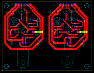
There's a simple little fix I thought of when having dinner with the XYL -- the IN and OUT pins of the 317 and 337 can be fixed up so that the board can be used with either device -- probably a very slight impedance bump with the vias. will work on tomorrow morning.
as Elvee stated pages ago, just reverse the direction of D1, D2 and the electrolytics and "bob's yer uncle"
as Elvee stated pages ago, just reverse the direction of D1, D2 and the electrolytics and "bob's yer uncle"
It would be GREAT if someone would make up a PCB design for the denoizator (both polarities) that would fit on a typical LM317/337 bipolar regulator board. Maybe then make a bunch of boards and offer them for sale? I have at least a dozen different pieces of gear with these sort of supplies in them that would benefit greatly from this modification!
It would be even greater if that "someone" was you: you seem to have relatively large needs, which makes a largish batch production advantageous, and you could sell the surplus to other members.It would be GREAT if someone would make up a PCB design for the denoizator (both polarities)
Personally, I am not a commerce guy, even for the good cause, even for no profit, and I have built the two I needed on bits of perfboard in less than a hour, I see no advantage going the hassle of designing, ordering PCBs for such modest needs.
Of course, if someone designs and sells PCBs, I will probably buy a pair for future needs, and I don't mind paying a reasonable supplement for the work involved.
Note that unlike the nonoiser, the denoizator PCB is absolutely identical for both polarities: you simply need to reverse diodes, Ecaps and use a BC327 instead of a 337.
This means that you could make a panel of 12 pieces for example, and cleave them in pairs or singles and populate them according to your needs.
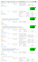
China PCB fab quotes $0.89 per board including shipping to New Jersey. DHL rings your doorbell with the delivery, 11 days after you upload the PCB CAD files. qty=100 price. I told them the board was 3.00" by 4.00" (a guess).
The website pcbshopper dot com is your friend.
_
The website pcbshopper dot com is your friend.
_
Attachments
The principle should also work for the 338; the details might be different, in particular the compensation components.@Elvee: will the D-Noizator circuit work for LM338?
If you make a PCB, I recommend you include a provision for a resistor in series with the compensation capacitor: you might end up strapping it, but if you play with the capacitor value and the resistor value (probably between 0 and 100 ohm), you will almost certainly find a correct stability range.
Almost is no certitude of course, and only an actual test will tell the definitive truth.
Thanks for the pointer Mark, it will certainly be useful in the future (let's hope Dotneck also finds it useful)China PCB fab quotes $0.89 per board including shipping to New Jersey. DHL rings your doorbell with the delivery, 11 days after you upload the PCB CAD files. qty=100 price. I told them the board was 3.00" by 4.00" (a guess).
The website pcbshopper dot com is your friend.
_
The principle should also work for the 338; the details might be different, in particular the compensation components.
If you make a PCB, I recommend you include a provision for a resistor in series with the compensation capacitor: you might end up strapping it, but if you play with the capacitor value and the resistor value (probably between 0 and 100 ohm), you will almost certainly find a correct stability range.
Almost is no certitude of course, and only an actual test will tell the definitive truth.
Thanks for the response, Elvee.
I already have two LM338-based power supplies powering an Allo Sparky and an USBridge. Someone built it for for me. I believe both are straight ahead datasheet implementations and they already sound better than the supplied wallwart.
I'm keen to rig up the D-Noizator on a general purpose board (like you did).
I am curious as to how you got such a low noise figure to begin with. The 317 data sheet lists noise as 0.001% of the output voltage. Unless I am somehow figuring this incorrectly, for a 15-volt supply, this would be 150 µVolts----WAY higher than the 16µVolts you measured.A simple circuit that transforms a good, clumsy workhorse like the LM317 into a superreg so easily that you do not even need to cut a single track.
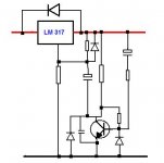
Let us start with the basic regulator (including the additional bypass cap, since we strive for the lowest noise).
Now, let us add the D-Noizator piggy-back:
The floor drops by more than 30dB.
The circuit works by changing the output node into an AC virtual ground.
Therefore, benefits do not stop at internal noise reduction: all the performances benefit: PSRR, output impedance. Ultimately, the performances are limited by the discrete transistor.
What about the reality? I made a test with ST and ONsemi samples. They behave as perfect clones, both with and without the D-Noizator.
With just the cap, the noise is 16μV, as measured by a Levell TM3B. With the D-Noizator, it falls to 2.5μV~3μV
An important thing to take into account (I already mentionned it somewhere in the thread) is that I compared the denoiser with the best possible standard 317 implementation, ie. with the capacitors.
The capacitor reduces the effective noise gain to unity, meaning the value measured will always be for a 1.25V regulator, independent of the actual DC output voltage. This explains the ~1:10 discrepancy.
Something else to take into account is that when I mention the total rms noise, it is always for 10Hz to 10kHz bandwidth.
And finally, the 2.5µ to 3µV figure has been updated later, when my LNA became operational.
I don't remember the updated value, but it is better, and it is in the thread
Edit:
Here it is: around 0.66µV
Re-edit:
This was not the final measurement, it was made with a temporary arrangement. The final value is even better (and it is also somewhere in the thread)
The capacitor reduces the effective noise gain to unity, meaning the value measured will always be for a 1.25V regulator, independent of the actual DC output voltage. This explains the ~1:10 discrepancy.
Something else to take into account is that when I mention the total rms noise, it is always for 10Hz to 10kHz bandwidth.
And finally, the 2.5µ to 3µV figure has been updated later, when my LNA became operational.
I don't remember the updated value, but it is better, and it is in the thread
Edit:
Here it is: around 0.66µV
I have been able to refine the measurements: I remembered that one channel of one of my lab amplifiers is equipped with a OPA27.
This brought the noise floor of my test set-up to 0.75µV.
When measuring the D-noizator, I got 1.0µV.
This means that the actual noise is in the vicinity of 0.66µV.
Since the noise with the cap connected normally is still 16µV, the improvement ratio is 27.7dB, much closer to what the sim predicted.
Of course, the test is made on a breadboard, and the transistor is just an ordinary BC337-40 from Philips.
With a good PCB and a super low noise transistor, it would be possible to scrape a few tens of nV
Re-edit:
This was not the final measurement, it was made with a temporary arrangement. The final value is even better (and it is also somewhere in the thread)
Last edited:
The cost per board, the one pictured below poz and neg -- about $6.60 for 100 produced in the US including shipping and sales tax. I am awaiting a quote from China.
I think C6 needs rotated 180 in the silk on the LM337 side.
Yes indeedI think C6 needs rotated 180 in the silk on the LM337 side.
Thus, the latest and final(?) noise level in a 10Hz to 10kHz range is 0.3µV.I have now remeasured the output noise in good conditions: it is <0.3µV in a 10Hz to 10kHz bandwidth;
nothing particularly exceptional, but it all depends on the auxiliary transistor, an ordinary BC337 in this case.
The figure could be improved by using a really high performance, low noise transistor
It could be very marginally improved using a better transistor, but even with a perfect transistor, the improvement will remain marginal: the denoiser reaches its limit, dictated by the 317's noise and the gain.
To do better, you would need to switch to the nonoiser, but implementing it on existing designs is going to be much more complicated (and probably not worth the trouble)
Thanks! Fixed that.I think C6 needs rotated 180 in the silk on the LM337 side.
I will email the gerbers to anyone who PM's -
")
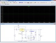
On our local DIY forum some guy did designed workbench power supply with lm317,external pass BJT,current limit that goes up to 50V, and added denoiser to it, simulated in TinaTI and it looks really good. Other member made it, everything works just like in simulation but he don't have equipment to measure noise.
Yes, for the protection against input and output shorts, the two regular diodes should be used.Hey LV , another question.
Often I see a diode to protect the LM317 when a big noise reduction cap is used.
The cap is pretty big here with the DeNoiser : 220 uF. Shouldn't there be diodes to not only protect the LM but the transistor too at switch off ?
If the supply to upgrade already has the Cadj cap, it will probably have the diodes too.
If the designer deemed them unnecessary, they are not necessary either with the denoiser.
If they are included, it is preferable to add the transistor protection diode: it will protect it against a dead short at the output.
Note that D1 and Q1 are much more robust than the internals of a 317: the Ifsm for the 1N4148 is 2A, and although the peak collector current of the BC337 is only 1A, it can probably also withstand 2A under majority carriers operation (but a short will kill both of them)
You mean something like this?And, LV, one more:
Any caveats to using the DeNoiser with a slightly higher voltage (37 volts) and much higher current (7 amps) regulator (uses external pass transistors)? Should I scale up the resistor values?
It seems to work in simulation, but since the transistor modifies the loop characteristics of the 317, the reality might be different.
In particular, it might be necessary to modify C4, and to add a small series resistor (0 to 100 ohm) with it.
BTW, I now recommend a larger value of C4 for any version: 10 to 22nF.
The HF noise reduction is slightly affected, but the stability is improved.
I do not recommend scaling up the resistors values: it will reduce the performances.
The only adaptation necessary is to use a powerful enough resistor type for R4: for 37V, 0.5W is sufficient (you can use 3/4W or 1W to have some margin)
Attachments
- Home
- Amplifiers
- Power Supplies
- D-Noizator: a magic active noise canceller to retrofit & upgrade any 317-based V.Reg.