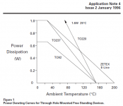
Here is some data from the manufacturer, about the ZTX851 transistor. I've also attached their Application Note 4 which discusses their proprietary, better-than-TO92 package, which they call "E Line", used on the ZTX851 and other Zetex devices.
_
_
Attachments
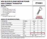
I have tested the BD's, but they don't perform particularly well (a bit better than the BC547 series, but not as good as the BC337).Fun fact about the ZTX851 : 5 A in TO92 ....huh , what ?
BC337 800 mA.
Just one more request : BD139 , often used in amplifiers .
The 2SC6043 and even a cheapo S8050 bought from Banggood for a cent or two did better (but didn't challenge the ZTX supremacy).
If you parallel a number of BC337 or S8050, you can also gain an improvement, 3dB for each doubling.
With 4 (preferably matched) 337, you could marginally outperform a ZTX
In principle: yes, and also in principle the benefit would be great compared to a "straight" (no additional caps) Maida regulator, because the divider ratio for a HV regulator (which is the main target of Maida's) is large, meaning the potential noise gain is high.
However, most implementations of Maida use bypass caps already, meaning the actual gain will be limited to 30dB, plus the cap-coupled amplifier will need bullet-proofing to withstand HV mishaps, and nesting additional circuits around an already overburdened 317 does not look like the best of ideas (could certainly be made to work, but is it worth the effort?).
I am not a fan of Maida-style regulators anyway, because the need to cocoon the poor little 317 from the brutal HV requires many additional complications to be half-safe, and the dropout voltage is absolutely horrendous: the 317 itself does not shine in this respect, but when you add the dropout + regulation margin of the cocoon transistor, you end with around 10V, which even for a HV supply is atrocious.
For HV circuits, it is better to start from scratch, and design something specific.
There are many examples on this forum and elsewhere, and I have described a number of examples.
Elektria, in my signature is one of them: in its basic form, the PSRR, noise and output impedance are not extraordinary, but it is inherently LDO, inherently rugged because it does not include low-voltage parts in the HV path, and it lends itself to higher-performance improvements where needed, be it noise, DC accuracy, output impedance, etc.
It is just an example: when you design for HV, do not adopt low-voltage idiosyncrasies, think HV from the start
Last edited:
Everyone has his pet circuits...
Compared to yours, the nonoisator has half the dropout, half the wasted power, a 15µΩ output impedance, and the 125dB PSRR is meaningful and useful, because its internal noise is commensurately low (down to 90pV), and does not drown the good PSRR.
It also supports Kelvin connections, which is essential at that level of performance.
Measure the output impedance with 150 ohm load -- this will render an "apples-to-apples" comparison with the 1995 AD797 SR.
Zout at this low level (as I found), is quite challenging and the AD797 has its own set of challenges!
I will make the measurement, but it will take some time: to reassemble the test setup, and to adapt the stimulus current, because 100mApp is unrealistic with an output current reduced to 80mA.Measure the output impedance with 150 ohm load --
With 16mApp, the output will be even lower, and I may need a frequency selective measurement to work in good conditions.
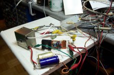
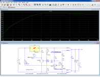
OK, here is the test setup:
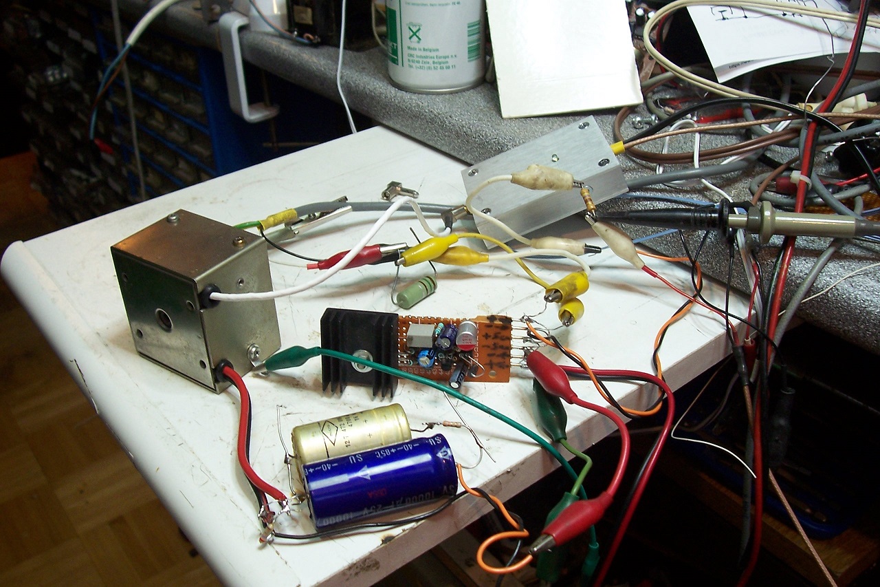
The large 150 ohm resistor is the DC load, and the smaller 470 ohm is the stimulus injector (16mApp, 1KHz).
This is the measured output signal, amplified 100,000 times.
It is quite dirty and noisy, even after some LP and HP analog filtering to remove most of the crud:

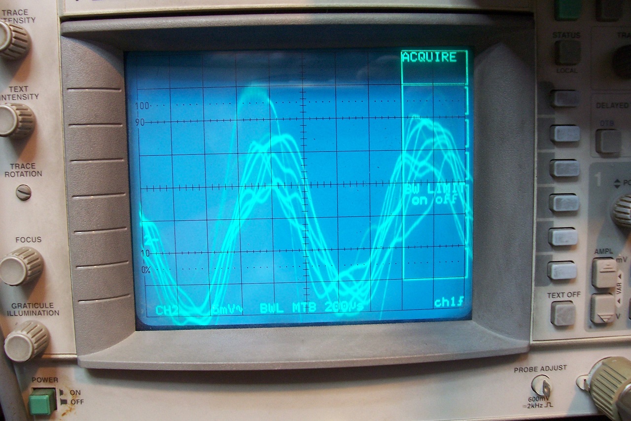
Fortunately, it is possible to get a clean waveform using the averaging function of the scope synchronized directly on the signal source:
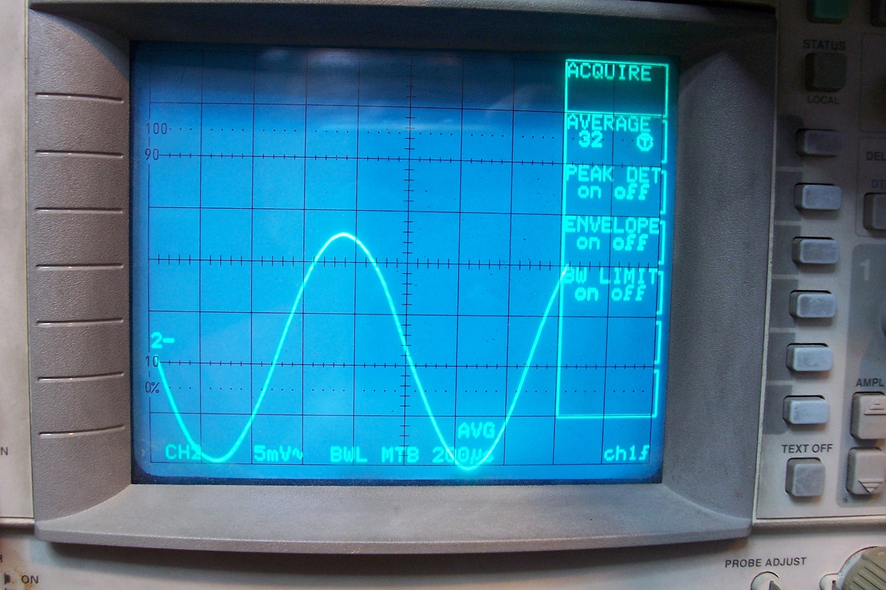
The amplitude is thus 4.5div x 5mV =22.5mV
When the amplification is factored in, the amplitude is 225nVpp.
Thus, the impedance is 225/0.016=14,000nΩ=14µΩ
The value is lower than that measured with 500mA output, but I suspect it has to with the ambient temperature, which is now 33°C.
The nonoiser makes the performances mostly independent from the regulator it is attached to.
The large 150 ohm resistor is the DC load, and the smaller 470 ohm is the stimulus injector (16mApp, 1KHz).
This is the measured output signal, amplified 100,000 times.
It is quite dirty and noisy, even after some LP and HP analog filtering to remove most of the crud:
Fortunately, it is possible to get a clean waveform using the averaging function of the scope synchronized directly on the signal source:
The amplitude is thus 4.5div x 5mV =22.5mV
When the amplification is factored in, the amplitude is 225nVpp.
Thus, the impedance is 225/0.016=14,000nΩ=14µΩ
The value is lower than that measured with 500mA output, but I suspect it has to with the ambient temperature, which is now 33°C.
The nonoiser makes the performances mostly independent from the regulator it is attached to.
Attachments


Remarkable invention, I have an application in mind right now!
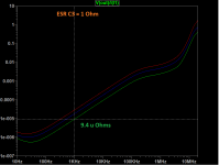
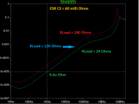
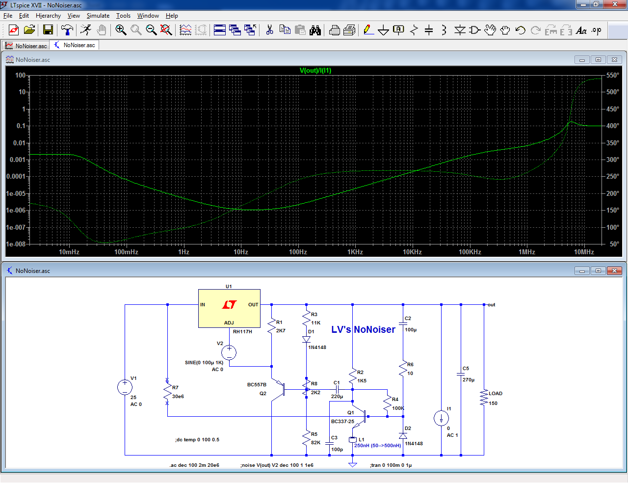
I just ran some simulations of output impedance, stepping the load resistor 24, 120 and 240 Ohms, using only 10uA AC load current (rather than AC=1).
The ESR of C3 might need a little bit of help with some external resistance, i.e. additional snubber resistor (the Panasonic FC I use are around 83 milli Ohm). Not a spot in which to use a Silmic or Muse.)
Edit -- I wish that WJ had taken pix of his impedance measuring test setup.
Attachments
Last edited:
AFAIK, small signal is small signal, even if you decide to use AC=10kA, and the circuit is biased in the µA level (but I could be wrong, or there might be some unexpected LTspice quirk).I just ran some simulations of output impedance, stepping the load resistor 24, 120 and 240 Ohms, using only 10uA AC load current (rather than AC=1).
This means that the scales or units might change, but the effective result should remain unaltered.
Things are completely different for DC sources, of course.
In the real world, I used a reasonably low stimulus, because at higher levels non-linear effects would begin to kick in.
I see the designator C3 only in the bootstrapped version of the nonoiser -which has not been physically tested- , and it seems that ESR there would have very little effect unless it is really excessive.The ESR of C3 might need a little bit of help with some external resistance, i.e. additional snubber resistor (the Panasonic FC I use are around 83 milli Ohm). Not a spot in which to use a Silmic or Muse.)
Edit -- I wish that WJ had taken pix of his impedance measuring test setup.
If you mean C5 (output cap), the one I used in the sim has 0.1 ohm series resistance, and the physical one is an organic polymer having a measured ESR of just 20mΩ @10kHz.
Of course, when you arrive at this level everything counts: the actual losses of the compensating ferrite bead, the layout (including the all-important mutual inductance effects between "tracks", or conductors in the case of my proto), the exact components used, etc.
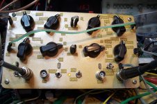
BTW, this measurement was made using the Chinese S8050 transistor.
I didn't investigate abnormalities in the MHz range, but if something really obvious had been present, I would have noticed it because my LNA has a sufficient bandwidth, and it would have been visible in some way.
I will have a more specific look now that the setup is operational again (but I don't expect big surprises)
I have made a sweep between 0 and 20MHz.
Under small-signal conditions (20mApp), I noticed some impedance quirks in the MHz range, but nothing comparable to the sim.
Upon closer examination, I realized that the output layout was not optimized for high frequencies: in particular, the stimulus injection was made 2~3cm away from the output bypass cap.
When the injection point was moved directly to the cap, all the oddities disappeared.
There was a steady increase of the impedance with frequency, but it was completely uniform, and beyond ~10MHz, the behavior was dictated solely by the bypass cap and the layout: it remained identical with or without power applied.
I also made a test for large signal conditions: Ipp~=Iout DC.
When the frequency reached ~400kHz, the error amplifier began to saturate and lose the control, resulting in a DC shift of the output and residues appearing.
This behavior could be mostly eliminated by connecting a 100pF cap between the collector of Q1 and the GND:
This very slightly increased the high-frequency impedance (between 100kHz and 10MHz).
In practice, for audio applications it is not necessary to do anything unless the supply is used for very special purposes, like a class B amplifier for HF magnetic loop systems (used in simultaneous translation) for example.
Attachments
@Elvee
I have a question about nonoiser. I have made TinaTI simulation and startup time is quite long. Output voltage slowly rises.It takes around 25 secs, then it goes overshot(1V above set value), then falls down and after 110 secs it reaches set value. One my friend got same results and he's really expert in TinaTI and knowledge of electronics. Is circuit supposed to work like this or in reality startup time is faster?
P.S.
I have been busy with job related projects so i didn't had much time to finish PCB for HP428 current probe.
@Elvee
I have a question about nonoiser. I have made TinaTI simulation and startup time is quite long. Output voltage slowly rises.It takes around 25 secs, then it goes overshot(1V above set value), then falls down and after 110 secs it reaches set value. One my friend got same results and he's really expert in TinaTI and knowledge of electronics. Is circuit supposed to work like this or in reality startup time is faster?
FWIW -- I am seeing the same result -- very slow startup time.
Yes, that issue (or feature: some people would be ready to kill beloved ones just to get a slow-start!) has already been mentionned: it is part and parcel of the nonoiser and to a lesser extent of the denoiser.@Elvee
I have a question about nonoiser. I have made TinaTI simulation and startup time is quite long. Output voltage slowly rises.It takes around 25 secs, then it goes overshot(1V above set value), then falls down and after 110 secs it reaches set value. One my friend got same results and he's really expert in TinaTI and knowledge of electronics. Is circuit supposed to work like this or in reality startup time is faster?
It is caused by the large time constants required to eliminate noise well below the subsonic frequencies.
The overshoot is caused by the (relative) proximity of the poles of the correcting amplifier.
Opting for different values of C1 and C2 could alleviate this particular aspect, but as always there would be other tradeoffs: even longer settling time, or reduced VLF rejection.
A 1V overshoot seems tolerable (to me).
If the startup time is an issue, it can be sped up by adding non-linear components to force initial conditions, but the task is not going as simple as it seems.
The overshoot could also be eliminated by strategically locating a zero in the response, but given the time constants involved, it is probably not going to be as simple as it sounds..
I will think about it anyway
Attachments
- Home
- Amplifiers
- Power Supplies
- D-Noizator: a magic active noise canceller to retrofit & upgrade any 317-based V.Reg.