The semi-discrete nature of the denoizator and the nonoiser allows two cheap tricks that fully integrated regulators cannot afford (contemporary ones at least: dinosaurs like the 723 did use it): large, discrete capacitors and discrete transistors.If really as low as 300nVrms , TI and LT can close down some of their regulator production lines . Who wants these expensive chips that have 10 times or more noise than a simple LM317 and a transistor ?
With capacitors, you can process the AC part without having to worry about DC performances and stability, and discrete transistors, even humble ones can have quite good noise performances in simple circuits.
When you need to include DC everywhere, it brings huge constraints.
The downside of cap-coupled circuits is that at some point in frequency, they will cease to function, but for audio it is perfectly acceptable to keep the good performances down to, say 5Hz, or any arbitrarily low frequency.
For a GP regulator, that is not possible.
The output voltage of the nonoiser can be computed with this expression, based on this schematic:
Vout = Vd + ((Vref+Vbe-Vd)*(R3+R8+R5))/(R3+R8/2)
Vd is the forward voltage of the compensating diode, typically 0.5V @ 110µA
Vref is the internal reference of the 317, typically 1.25V
Vbe is the base-emitter voltage of the buffer transistor, typically 0.7V
R1 is independent of the output voltage, and R3 can vary a little about 11K, to arrive exactly at the desired output voltage, but it is normally comprised between 10 and 12K.
The main resistor acting on the output voltage is R5, so we can rewrite the expression to yield R5:
R5 = (R3*(Vout-Vref-Vbe)+R8*(Vout/2+Vd/2-Vref-Vbe))/(Vref-Vd+Vbe)
If we use the typical numerical values and make R3=10K and R8=2.2K, the expressions become:
Vout = 0.5 + (17.69+1.45*R5)/11.1
R5 = (11.1*Vout-23.35)/1.45
Last edited:
^ So with R5 =82k , the Vout on your schematic is 12,8054 V ?
Now I always go overkill with capacitors on both sides of the regulator . What if I add a 1000uF or even a 4700 uF, the usual ones not the low ESR's , and some 100 nF to 1uF ceramics and a 2,2 uF MKT on the DeNoiser's output ? (With only some 50 mA to 100 mA output current to Opamps ).
Now I always go overkill with capacitors on both sides of the regulator . What if I add a 1000uF or even a 4700 uF, the usual ones not the low ESR's , and some 100 nF to 1uF ceramics and a 2,2 uF MKT on the DeNoiser's output ? (With only some 50 mA to 100 mA output current to Opamps ).
Last edited:
No, because the simplified formula assumes 10K for R3 (it is an E12 value), but the example was targeted at exactly 12V, and used the room for manoeuvering between 10 and 12K to end with 11K, an E24 value. (I also gave the complete formula above)^ So with R5 =82k , the Vout on your schematic is 12,8054 V ?
In front of the regulator, do as you like: more is better, the ripple will be mechanically reduced by increasing the capacitance.Now I always go overkill with capacitors on both sides of the regulator . What if I add a 1000uF or even a 4700 uF, the usual ones not the low ESR's , and some 100 nF to 1uF ceramics and a 2,2 uF MKT on the DeNoiser's output ? (With only some 50 mA to 100 mA output current to Opamps ).
At the output, you have some room for increase, but don't go overboard, and don't stack many parallel capacitors of different values.
It is perfectly OK to add a local bypass at the point of load, after several inches of wiring for examples, but clustering many different caps in a single spot is definitely counterproductive, especially if their capacitance ratio is large: greater than 100 to 1 is always problematic because of unwanted resonances.
Make a search on the forum if you are not convinced: many people (including me) have given hard, quantitative examples of problems arising from parallel caps.
Last edited:
So are you planning to test the LM337 with the DeNoiser (and the NoNoiser) , in
real life not a software simulation ?
What do you think about using 2 positive regulators instead of the usual positive
and negative for +15/-15 V audio circuits , like I've seen some do ... even Elektor.
It would keep de pos & neg identical , which the LM317 and 337 not really are.
Are you planning to do some upgrades to the newer types of LDO's ? I mean , if
the noise number you give are reproduceable by others , it is pretty awesome for a
simple and easy (and cheap) upgrade of the LM317 , only 2 minor advantages I see
with the expensive LT & TI low noise regulators , that is : they are low dropout and
most have a shutdown/enable function.
No, not at the moment, but that could change (if I need one for a project, for example)So are you planning to test the LM337 with the DeNoiser (and the NoNoiser) , in
real life not a software simulation ?
It should be possible too, and the general principles would remain the same, but I expect some differences, in the compensation strategy amongst other things, because as you point out, 317 and 337 are not mirror images.
It has the advantages of a perfect symetry, a simplified BOM, but it also brings some constraints: you cannot use a regular center-tapped transformer for example.What do you think about using 2 positive regulators instead of the usual positive
and negative for +15/-15 V audio circuits , like I've seen some do ... even Elektor.
I may try it, but I expect much greater difficulties....Are you planning to do some upgrades to the newer types of LDO's ?
This could interest you:I mean , if
the noise number you give are reproduceable by others , it is pretty awesome for a
simple and easy (and cheap) upgrade of the LM317 , only 2 minor advantages I see
with the expensive LT & TI low noise regulators , that is : they are low dropout and
most have a shutdown/enable function.
Just for fun: a superreg with <12 discretes??! ?! ?
It is completely discrete, meaning you can add all the functions you need, it is reasonably low dropout, and you can build a perfect mirror image using complementary transistors
Since you brought up discrete regulators , I' ll try not to go off topic too much . I'm more into the voltage ref + opamp kind of circuit , because I've made some of them for digital circuits not audio.
In the early 90's there were no good low quiescent current , low dropout regulators. Maxim and Intersil had some uPower CMOS regulators , sure , but they sucked . The LM2940 types were awful with large PNP base current , so I made my own LDO's with the awesome TLC271 for mostly battery powered cicuits. A 5,6 V zener with LM334 CC source or a LM336-5V and a high Hfe PNP like BC337/327 or BC161 , later with low Rdson PMosfets for high current output. Worked great , but of course I've never measured the noise. An added bonus is that you keep the heat away from the V-ref and the opamp , just the transistor gets some cooling when needed.
Making it yourself for audio , is different . Staying below or not much above 6 $ of current regulators , is not easy . A cheap (< 2 $) ultra low noise opamp like LM4562 ok , but an ultra low noise V-ref is imposible to find for little money. The ones I found don't come near your 300 nVrms of the DeNoiser.
Ultra low noise V-refs are usually combined with high precision , low drift and those are more expensive . Also less choice if you want 10 V refs . Moreover , 10 V refs are usually derived from , yes ...1,2 V bandgaps ! Just what I try to avoid. Of course you can take a cheap TL431, put it at the voltage you want and filter it hard to make it very low noise . Absolute value and temperature drift are not a concern with opamp amps like preAmps or HP amps. Add a low noise PNP like BC337 ( for low currents) and the usual R's and C's and it should be ok ... but I have no way of testing the true noise , PSRR , transient response and whether Mosfets are lower noise than bipolars as output regulator transistors. There are the circuits designed by others , but often they don't give the spec's . Some will think about short circuit current protection ... but really , do you need that with delicate audio circuits ? Just be careful you don't short things while measuring. Worst case , transistor and opamp replacing , since they're not the dreaded 3x3 smds , no problem. Switching on and off by shorting the V-ref, slow ramp start voltage , same transistor with an RC on the base . Easy. Those discrete ones in your link are not ... for me.
Tastes and colors....
BTW, I tested the LDO hypothesis in sim, and to my surprise, it seemed to work with very minor tweaks:
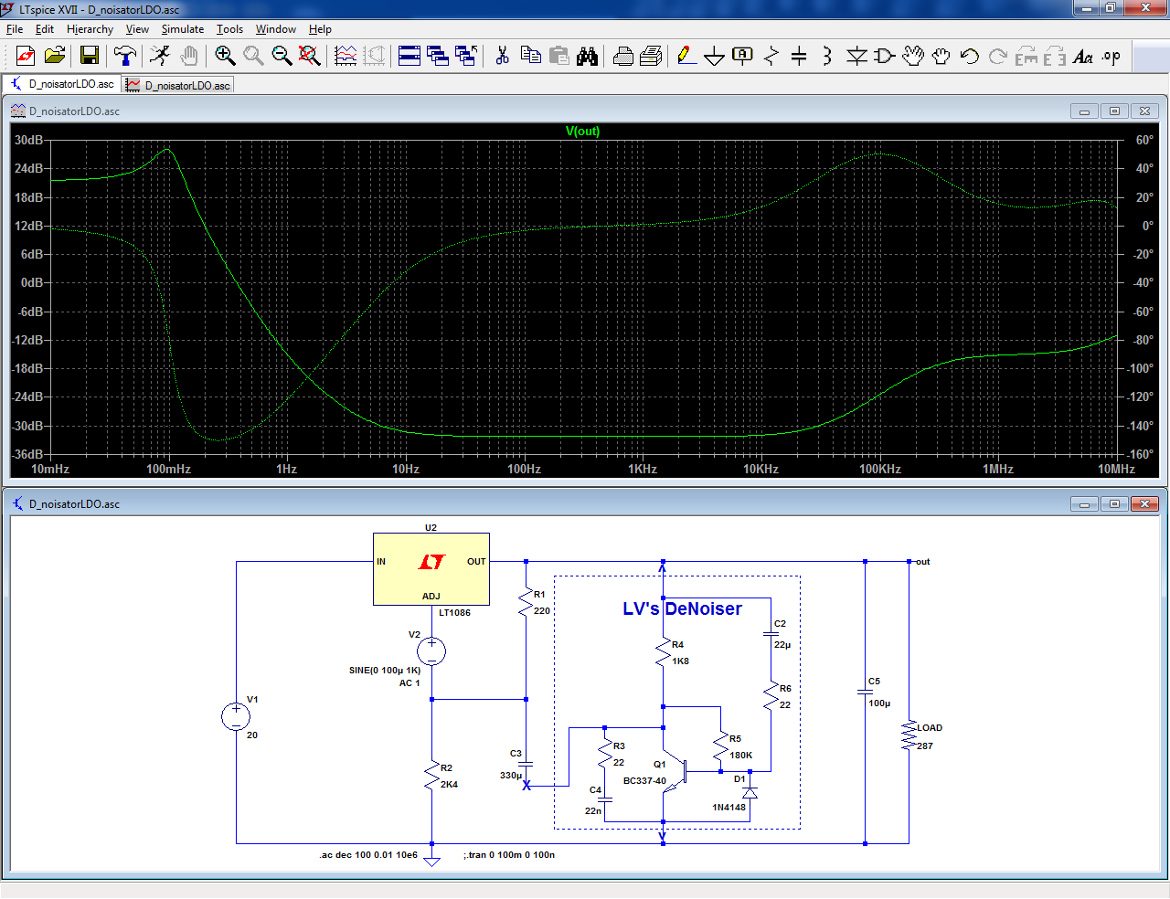
The tweaks remain perfectly compatible with a regular 317, and it could even benefit from them.
Of course, it is just a sim, and the reality could be less rosy, but since it is a IC from Linear/ADI, one can realistically expect a good agreement between sim and reality.
The improvement is the same 30dB as for the 317
BTW, I tested the LDO hypothesis in sim, and to my surprise, it seemed to work with very minor tweaks:
The tweaks remain perfectly compatible with a regular 317, and it could even benefit from them.
Of course, it is just a sim, and the reality could be less rosy, but since it is a IC from Linear/ADI, one can realistically expect a good agreement between sim and reality.
The improvement is the same 30dB as for the 317
Attachments
So that's about 30 times less noise with the DeNoiser . LT1963A's datasheet gives 200uVpp 10 to 100kHz (page 11), for 15 V out that's nearly 1mVpp or 400 nV/rHz , with the Denoiser approx : 330uVpp or 130nV/rHz or 50 uVrms ? (all for 15 V out 10Hz to 100kHz) . Against your 300nVrms with the LM317. My numbers must be wrong .
We probably don't have the same datasheet: here is what I found page 9:

I wouldn't rely too much on the P to P visible on the oscillogram, since the total rms noise (15µV) and the spectral noise density are also given (40nV/√Hz).
These values will be divided by ~30 with the denoiser since the result is higher than the denoiser's own floor, so 500nV rms total noise for a 100kHz bandwidth, but the measurements I made were for a 10kHz bandwidth, so the extrapolated/100kHz value for the 317 + denoiser should be 300nV*√10~=1µV
Attachments
I just downloaded a fresh one , and yes there it's on pg 9. There is no date on the LT datasheets (TI does have dates ... or revision dates) . But those are the same graphs . It differs greatly for a 3,3 V or a 15 V output voltage . Those oscilloscoop pics are usually accurate , so here it is 200 uVpp for 3,3 Vout = approx x4,5 for 15 V = near 900uVpp or divided by around 6 = 150 uVrms . The 15 uVrms you mention is the 1,5V out version or the adjustable version at 1,22V (the minimum output =bandgap Voltage) , 15 V out is then 10 times the noise of 1,5 V version = 150 uVrms . Again let's take the 1,5 Vout version : 0,5 uV/rHz x 10 (for 15 V out ) = 5uV/rHz all for 10 Hz to 100kHz. TI and LT are pretty clear that the noise is proportional to the output voltage. You see it in the graphs and they often mention it in the text with the application information. I think they don't like to show the graphs or numbers with a 15 or even 18 V out , because it is NOT so great ! Maybe the DeNoiser is noisier with high output voltage too ?
So with the 1963 + DeNoiser it's going to be 5 uVrms ... still 5 times more than the LM317's 1uVrms , for 4x the price.
So with the 1963 + DeNoiser it's going to be 5 uVrms ... still 5 times more than the LM317's 1uVrms , for 4x the price.
Last edited:
Yes, and the reason is obvious: when you add an external resistive divider, you change the VR into an amplifier amplifying its own noise, with a gain equal to the ratio of the divider.The 15 uVrms you mention is the 1,5V out version or the adjustable version at 1,22V (the minimum output =bandgap Voltage) , 15 V out is then 10 times the noise of 1,5 V version = 150 uVrms . Again let's take the 1,5 Vout version : 0,5 uV/rHz x 10 (for 15 V out ) = 5uV/rHz all for 10 Hz to 100kHz. TI and LT are pretty clear that the noise is proportional to the output voltage.
I only took the base noise into consideration, because you always have the option of bypassing one of the resistors with a cap, as in a 317 (the poor man's denoiser?)
No, because the denoiser realizes an implicit bypass, and this bypass and the gain are broadly independent from the supply voltage.Maybe the DeNoiser is noisier with high output voltage too ?
In fact, because an increased supply also increases the transconductance of the transistor, the performances should marginally increase
the poor man's denoiser?
Well , going over all the datasheets of the "new and improved" regulators , I felt somewhat disappointed . You can get a LM317 & BC337 everywhere nearly for free . The LT & TI LDO's go from 3$ to >6$ and you need to order them.
So your "poor man's" DeNoiser came at the right time for my next project and some retro fitting.
By "poor man's denoiser" I meant the bypass cap.
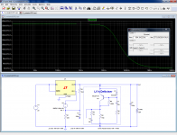
Since the LT1963 has a reliable model, it is possible to simulate the noise performance of all the options.
First, the plain vanilla regulator circuit, with just the two resistors in circuit:
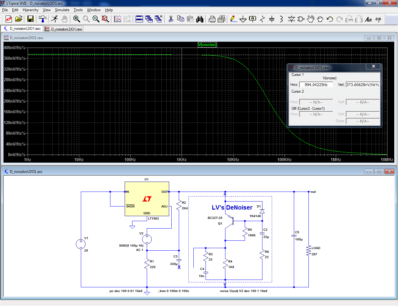
373nV/√Hz
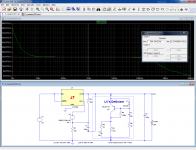
Then, the poor man's denoiser (bypass cap):
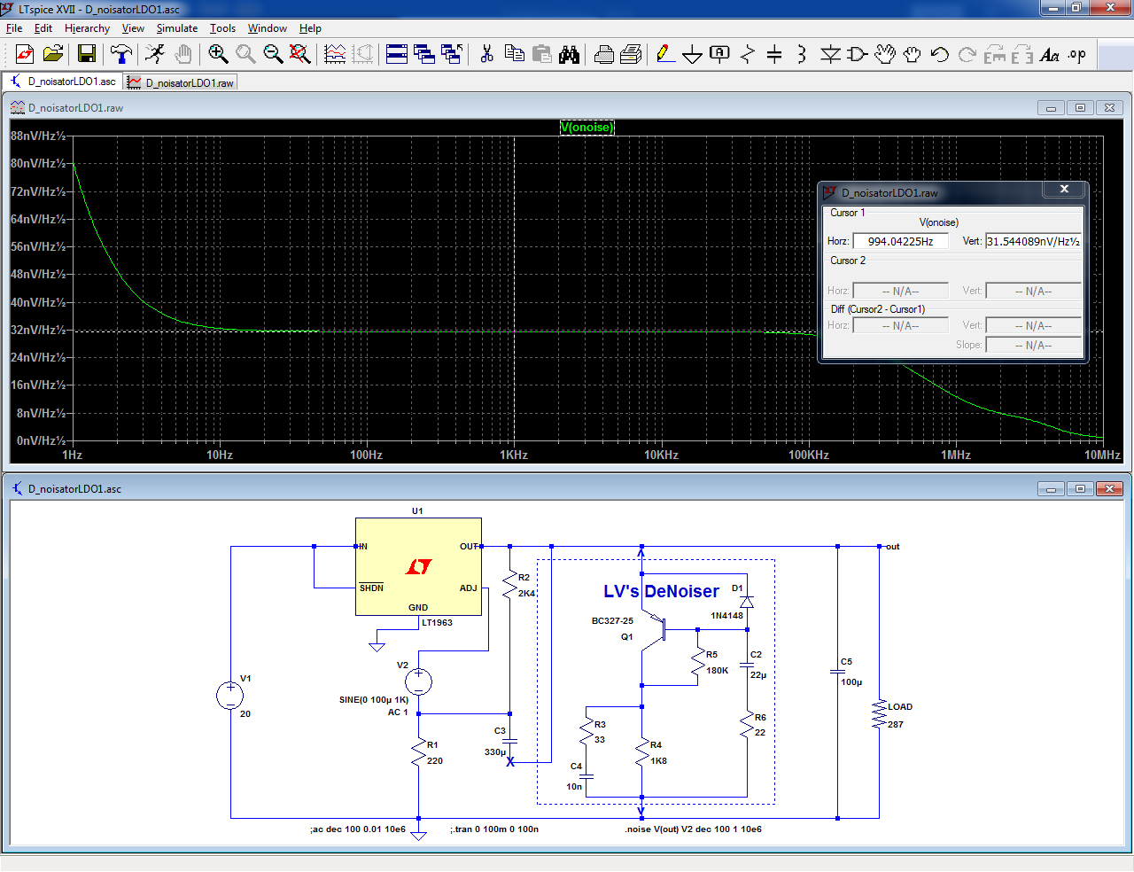
31.5nV/√Hz
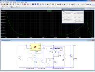
And finally, the complete denoiser in its full, glorious splendor:
1.04nV/√Hz
Since the LT1963 has a reliable model, it is possible to simulate the noise performance of all the options.
First, the plain vanilla regulator circuit, with just the two resistors in circuit:
373nV/√Hz
Then, the poor man's denoiser (bypass cap):
31.5nV/√Hz
And finally, the complete denoiser in its full, glorious splendor:
1.04nV/√Hz
Attachments
So that's a little better than the DeNoiser with LM317 +- 3nV/rHz to 1nV/rHz (but only simulated).
I like the p-p value better , which should be around 2uVpp vs 0,6uVpp . So for 5 $ more you get slightly less noise, low dropout and a shutdown/enable.
Does the PSRR get a boost too like the LM317 did ?
I like the p-p value better , which should be around 2uVpp vs 0,6uVpp . So for 5 $ more you get slightly less noise, low dropout and a shutdown/enable.
Does the PSRR get a boost too like the LM317 did ?
Yes, simulations are always a bit optimistic, and I expect the real value to be closer to 1.2~1.5nV. On the other hand, the values for the 317 denoiser are actually measured, and I have also measured other types than the BC337 as transistor:So that's a little better than the DeNoiser with LM317 +- 3nV/rHz to 1nV/rHz (but only simulated).
D-Noizator: a magic active noise canceller to retrofit & upgrade any 317-based V.Reg.
With a ZTX851, the noise falls to 0.16µV (~=1.6nV/sqrtHz).
The nonoiser reaches 0.09µV, but it is not easily retrofittable.
Yes, PSRR and output impedance are also 30dB betterDoes the PSRR get a boost too like the LM317 did ?
This thread should be pinned as the go to awesome performant AUDIO regulator. Once you get to these numbers for noise and PSRR ( < 2 uVpp & > 95 dB ) with a few easy, cheap ordinary components , there isn't much use for most of the 'special" regulators featured here on the Diyaudio forum , for preamps , HP amps , even MC/MM and microfoon amps. But that's just my opinion.
Yes , I've read about the various low noise transistors , but for people like me ordering online isn't always posible , so the ZTX851 and the others are not easy to get . The BC337 is . You tested BC547 (and PNP BC557), but not the slightly lower noise BC549/550 and 560 ? These are also in smd with an 8 : BC850.
Does the Hfe of these transistors count in the DeNoiser ? The A , B and C versions , or BC337-25 or -40 ?
Last edited:
"Special" regulators have plenty of uses, in metrology, instrumentation and similar fields where you need performance from exactly 0Hz (DC) to 100kHz or 1+Mhz, but for for audio applications, they are indeed wasted, since it is possible to use cheap tricks like the denoiser.
The BC550 series are "old generation", small area low noise transistors, performing reasonably well in low-current, relatively high impedance situations, but when you need raw noise performance (voltage noise), larger devices like the ZTX851 or even the BC337 are way better: the source impedance in the case of the denoiser is just the base protection resistor.
The Hfe only has a tiny effect: the base current value is mostly unimportant in this type of circuit, and although there is a negative correlation between Hfe and Early voltage (meaning A selections should have a higher 1/h22), the improvement in voltage gain is going to be negligible due to the low impedance seen by the collector, so the effect of the selection is ~nil, except that the bias needs to remain in linear mode, which is easy to achieve
- Home
- Amplifiers
- Power Supplies
- D-Noizator: a magic active noise canceller to retrofit & upgrade any 317-based V.Reg.