Many will use such a PSU for digital gear which demands other things of a PSU.
Jan-Paul I would appreciate if you can list PSU parameters to be tested for applicability.
George
Well I am pretty sure you can come up with that yourself.
Here are a few I (or we?) appreciate besides the standard things as high ripple rejection: high bandwidth, ultra low output impedance, low drop, ultra low noise, small size package (easy to solder is a bonus) and available in TO220, at least 1A capable but 3A would be very nice, 20V (36V would even be better) input voltage capability and unconditionally stable with low ESR caps ie ceramic caps at the output.
in other words a 1 and 3A version of LT3045 in TSOT and TO220 format And ... if it works OK in high speed digital and RF circuits chances are likely that analog circuits will benefit as well.
Just yesterday I heard an old Audio Note DAC 4 and the owner modified the unit so it would accept plug in modules for the digital +/- 5V . As time was scarce we only listened and choice was between New Class D and Tentlabs shunt PSU modules. Even though power draw is minimal the difference was easily heard. After 40 years of building and modding I am sure the first thing to think of in any audio device is an excellent PSU, be it for analog or digital circuits.
Here are a few I (or we?) appreciate besides the standard things as high ripple rejection: high bandwidth, ultra low output impedance, low drop, ultra low noise, small size package (easy to solder is a bonus) and available in TO220, at least 1A capable but 3A would be very nice, 20V (36V would even be better) input voltage capability and unconditionally stable with low ESR caps ie ceramic caps at the output.
in other words a 1 and 3A version of LT3045 in TSOT and TO220 format
And ... if it works OK in high speed digital and RF circuits chances are likely that analog circuits will benefit as well.Just yesterday I heard an old Audio Note DAC 4 and the owner modified the unit so it would accept plug in modules for the digital +/- 5V . As time was scarce we only listened and choice was between New Class D and Tentlabs shunt PSU modules. Even though power draw is minimal the difference was easily heard. After 40 years of building and modding I am sure the first thing to think of in any audio device is an excellent PSU, be it for analog or digital circuits.
Last edited:
I hope you heard about via stitching and shielding...i didn't showed the bottom pcb work i do on those double sided perboards but every single thing i do is worked exactly like a proffessional instrumentation amplifier ... It may not look as fancy as most people are used to, but i know how to get the lowest noise possible in a circuit.If you have read what i said in other topics i already told that i can make a phono and tape head preamps to have inaudible noise without the use of any voltage regulators. By the way...these perfboard you saw are the highest quality perfboard on the market.If you think that things on perfboard are able to compete with a double layer PCB with a modern regulator you are dreaming indeed.
There is no "good enough", we want the best out of our audio and the PSU is most important. Not to keep hanging in the past while way beter stuff is available out there be it DIY or ready made. Regs should work OK in the audio band but for DACs the regs should be able to cope with high frequencies too. Many will use such a PSU for digital gear which demands other things of a PSU. Not everyone uses 30 year old analog gear and is building LM317 stuff for it.
Thank you.Here are a few I (or we?) appreciate besides the standard things as high ripple rejection: high bandwidth, ultra low output impedance, low drop, ultra low noise,
I only wonder if a plot of output impedance out to some MHz (number?) is good enough to demistify applicability to DAC circuitry (apart from low noise and ripple rejection).
George
I intend to (measure, not simulate) but there will be a month delay from my part. That is, when I receive the modern packages.
>Edit. Meanwhile, info on the Zo of LM317
Simple Voltage Regulators Part 2: Output Impedance
Simple Voltage Regulators Chapter 2: Output Impedance
George
>Edit. Meanwhile, info on the Zo of LM317
Simple Voltage Regulators Part 2: Output Impedance
Simple Voltage Regulators Chapter 2: Output Impedance
George
It was only joking. I have tested many regs in various devices and powering every single section with its own local regulator and then also a good one is an instant improvement. Well it is not an improvement, it is a good design choice.
It is not about old versus new. It is about choosing what is best at the time one develops a device instead of using what is in a drawer or what one knows. I like LM723 very much and it is even today still a very good regulator but with too high part count, some drawbacks like it being not capable of more than 150 mA without pass transistor. Despite that I still use it for some purposes and so do manufacturers of measuring equipment apparently. Even LM723 beats 78xx and LM317 hands down for decades already! So if one likes dinosaurs then there was choice to choose the best one for more than 40 years
It is not about old versus new. It is about choosing what is best at the time one develops a device instead of using what is in a drawer or what one knows. I like LM723 very much and it is even today still a very good regulator but with too high part count, some drawbacks like it being not capable of more than 150 mA without pass transistor. Despite that I still use it for some purposes and so do manufacturers of measuring equipment apparently. Even LM723 beats 78xx and LM317 hands down for decades already! So if one likes dinosaurs then there was choice to choose the best one for more than 40 years
Last edited:
There's some people that would benefit from a diy version of denoisers.
I for sure recommend getting a nice power supply module if you want proven designs and don't want to muck about with etching and drilling holes and you can afford it.
Also you could fit two of the later designs on a 10cm X 10cm from jlcpcb, which costs under 10$ delivered for 5 boards. That's a bit under 1$ per final board but you need to cut the board in half (or make +- on a 10cm X 10cm board). You could put any two of the three circuits on 10x10cm board. The only downside is the wait time.
I don't think I'll use lm317 for the digital part of the DAC for example. I need to see other options there. Overshoot for 3.3V or 1.8V rails doesn't seem like a good idea.
Last edited:
in other words a 1 and 3A version of LT3045 in TSOT and TO220 format
Here's something that I'm pondering right now. Wouldn't a LM317 + denoiser be a good candidate to drop the grunt from 15V to let's say 7V for a later LT3042 to 5V AVCC? That way LT3042 doesn't have that much heat to deal with, while the LM317+denoiser cleans the supply and deals with the heat further from the DAC. 10V drop at 70mA is 0.7W of heat. Whatever noise is left the LT3042 can deal with. In this case overshoot is irrelevant for the few minutes.
Last edited:
One can also use a separate small 6V or 2 x 6V transformer and CLC filter. No unnecessary preregulator, less heat, green/eco. With a 2 x 6V one can power even 2 sections of a device each with its own PSU.
But to my surprise you are contemplating LT3042/3045. Forget about LT3042 and use LT3045 instead. For that small price difference 300 mA more current. It is indeed the regulator that cleans up the noise.
But to my surprise you are contemplating LT3042/3045. Forget about LT3042 and use LT3045 instead. For that small price difference 300 mA more current. It is indeed the regulator that cleans up the noise.
Last edited:
I'm looking at upgrading a DAC that I already have, I would like to use the case and transformer. I do have an extra 9VAC tap that would leave me with around 11VDC but if possible I'd use that for the digital side. DSP seems like it might need some more current than the analog side.
LT3042 is good as AVCC needs 60mA or so, and I include the 1-2mA for Vref in it, so 70mA is more than enough. 300mA extra wouldn't be useful here. Maybe in the digital part.
I am not against using certain parts. I'm doing an exercise in making it as cheap as possible and no more performant than needed in this application. It's an exercise.
I would love to be in the situation to go ham in with everything "just to put my mind at ease". You know, adding all the bells and whistles.
I like the challenge of trying to find smart and cheap ways to get the same result.
I understand the wish for low Zout that seems to be a must at high frequencies especially for DACs.
However, I think this must firstly be taken care at the IC bypassing caps.
This is where the need is actually and for best results as close as possible to the chips V supply pins.
This from the PSU is not an effective help because it cannot be as close as mm² ceramic caps, and is plagued by tracks inductances.
Best PSU performances, schematic topologie and simulation can be fascinating, but I think there is more to get bypassing with best caps technology and PCB layout.
https://www.google.com/url?sa=t&sou...FjAAegQIAhAB&usg=AOvVaw0iikQxNfFmR_wvzn7baPY5
Last edited:
https://www.diyaudio.com/forums/pow...it-upgrade-317-based-reg-127.html#post6361402Here's something that I'm pondering right now. Wouldn't a LM317 + denoiser be a good candidate to drop the grunt from 15V to let's say 7V for a later LT3042 to 5V AVCC? That way LT3042 doesn't have that much heat to deal with, while the LM317+denoiser cleans the supply and deals with the heat further from the DAC. 10V drop at 70mA is 0.7W of heat. Whatever noise is left the LT3042 can deal with. In this case overshoot is irrelevant for the few minutes.
Yeah seems to be like a good way to go about it. Tho I don't like the module idea for ultra low noise and precision. One: you need wires to get to the chip, and two: you loose the sense lines capability of the LT3042. Most modules don't have sense wires broken out.
Indeed it looks fancy to have them layout in modules.
Indeed it looks fancy to have them layout in modules.
You are very right. It looks fancy but they should have been in the design. Separate modules.... one can ask if the added wiring makes matters better or worse. For best performance the regs should be as close to the ICs as possible.
Therefor: when designing a new device like a DAC, make sure to use local regulators of the best quality one can find/afford directly at each section. Forget the old separate PSU idea with cabling.
Since many old fashioned devices use several 78xx or LM317 it would maybe a good idea to make LT3045 versions as the regs were close to the stuff in many cases certainly when it were 1 board designs .... just as an upgrade for old devices.
Last edited:
WE could take the same pictures but with these currents I would not worry too much but I would check with a simple IR meter as usual. Your application is a power amplifier and your testing was done with +/- 27V and 4A continuously for 90 minutes. That's 216W.
Why on earth NOT buy a hobbyist grade infrared imager and get hobbyist grade accuracy? It's not terribly expensive because they don't make you pay for a color display; that's on your smartphone which you already own. You'll have a lot of fun taking images and will feel greatly reassured if and when you see that your electrolytic capacitors are not excessively heated.
BTW the PSU board I tested, only dissipates about 6 watts itself -- the rest is dissipated in the electronic load used for testing. And boy does that electronic load contain a lot of fans! To calculate the power dissipated in the PSU board: 8 amps total (4 in the positive rail and 4 in the negative rail), times the forward voltage drop of the MBR10100 Schottky rectifiers (about 0.75V RMS thanks to the small conduction angle) equals 6 watts.
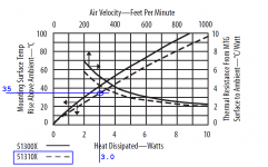
This matches the thermal imager results pretty well. The images say the heatsinks are 61C, while the air is 27C. Thus thermal rise is 34 degrees. The heatsink datasheet's curve attached below, shows that a thermal rise of 34 degrees corresponds to a dissipation of 3.0 watts per heatsink: see the blue circle. Since there are two heatsinks, the total dissipation is 6 watts. Check.
_
Attachments
So in effect the heat in the PSU design will likely be very low. I have my tools to measure temp (and had a FLIR at work) and I always do just to know what happens but I am not the one designing here.
If I would want a heat camera I would want a FLIR but it really does not pay off enough. Same goes for the equipment I already own.
If I would want a heat camera I would want a FLIR but it really does not pay off enough. Same goes for the equipment I already own.
Last edited:
- Home
- Amplifiers
- Power Supplies
- D-Noizator: a magic active noise canceller to retrofit & upgrade any 317-based V.Reg.