Thanks for the ZTX model.
Noise is calculated from RB RE RC.
Is RB=0.029 the know measured value ?
The model does not include:
AF and KF. These only affect low frequency (1/f) noise performance.
Can you give me the 2N3919 model.
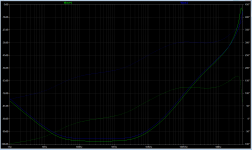
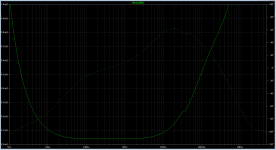
As expected with C4 100nF ( iso 22nF ) the PSRR is not as good at high frequencies.
Same at 100Hz -172dB
About the same at 1KHz ( 2dB lost)
-146dB at 20 KHz ( iso -158 )
-121 at 100KHz ( iso -133 )
I typed an error in a previous post:
Error: With C4 100nVF R7 0.2ohm it is stable with no output cap
Read ....C4 100 nF R7 10 ohm it is stable...
Noise is calculated from RB RE RC.
Is RB=0.029 the know measured value ?
The model does not include:
AF and KF. These only affect low frequency (1/f) noise performance.
Can you give me the 2N3919 model.
As expected with C4 100nF ( iso 22nF ) the PSRR is not as good at high frequencies.
Same at 100Hz -172dB
About the same at 1KHz ( 2dB lost)
-146dB at 20 KHz ( iso -158 )
-121 at 100KHz ( iso -133 )
I typed an error in a previous post:
Error: With C4 100nVF R7 0.2ohm it is stable with no output cap
Read ....C4 100 nF R7 10 ohm it is stable...
Last edited:
For the Q1 I just picked first PNP that can suit simulation, not the actual circuit (Vce is too low), so pick suitable one. For the sziklai I tried BD140+BC337 and it works well, as it will with almost any transistors pair.
I don’t remember where ZTX model is from and if all parameters are checked by measurements but AFAIK resulting circuit noise is close to real results.
High PSRR implies that you are using model with CCS in place of R1. Is this a LTSpice ideal current source model? I checked with LT3092 in place of R1 and there was no improvement but using generic ideal source gave very high PSRR, what may be unrealistic.
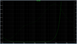
The CCS I use in the simulation is a LTSpice current source with a parallel resistance to represent the impedance of a real CCS.
My simulation shows best improvements with this // resistor > 100K and good improvements for > 10K.
A simple real CCS made with two BJTs has a dynamic impedance larger than 5000K.
May be it has a parasitic capacitance that should not be neglected in the simulation.
Edit: My simulations shows: Adding a small capacitor in // makes about no difference on PSRR at 100Hz 1KHz. With 100pF there is a 3dB difference at 20 KHz.
Last edited:
In my simulation using an ideal current source, I downgraded with 100K and 100pF in //, I do have near the same results as with an ideal source.I ( Tombo56) checked with LT3092 in place of R1 and there was no improvement but using generic ideal source gave very high PSRR, what may be unrealistic
Same stability and great PSRR improvement.
I do not understand what is going on with LT3092 which is way better than 100K//100pF as I see on the datasheet from the figure giving it's impedance versus frequency.
I will use cheap BJTs like 2N3904 2N3906.
These have Co < 4.5pF.
I know it raises at low Vcb, but I am confident my real CCS will have < 100pF parasitic capacitance.
I do not trust models, unless they are from trully serious sources.
There are tons of models on the net, most is junk, especially when looking for high performance.
LTSpice is an exact powerful calculator, no more.
I rather use defaults than supposed to be real components.
I hope the TL431 model I am using is trustworthy.
I hardly believe dBs beyond 140 in simulation results, I look more about trends.
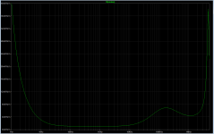
Replacing the R1 1K resistor by a 2 BJT ring CCS gives an improvement in PSRR of 46 dB.
There is no difference simulating with default LTSpice transistors or 2N3906 models.
To get a 4mA constant current the ring uses a 180 ohm emitter resistor. The biasing resistor is 40K.
No doubt, there is a worthwhile PSRR improvement, that will push residual 100Hz/120 Hz ripple to oblivion, but what about noise.
Noise from the CCS. Is the current noise turned into a small voltage noise thanks to the small TL431 impedance ?
This impedance is 0.2 ohm from the datasheet, so about 2.5 ohm when used for 32V ( iso 2.5V ).
Last edited:
CCS noise is for sure lover than TL431 uncompensated noise. Whatever noise CCS adds to the TL431 cathode point, is compensated by denoiser.
Later today (I’m still on work), I will add negative regulator solution with TL431, so we will have true electrically symmetrical solution.
Later today (I’m still on work), I will add negative regulator solution with TL431, so we will have true electrically symmetrical solution.
Negative regulator with TL431.
There is a catch. It cannot be done with the topology of the positive regulator, because the TL431 Vref = 2.5V is referred to the Anode.
An exact mirror would ask for a complementary TL431 that has the Vref referenced to the Cathode.
Complementary TL431 doesn't exist. It is not needed when used as a Zener, but here in the positive regulator, the TL431 is not set up as a Zener, the upper resistor doesn't go at the Cathode, but goes to the output port.
All this, is why, if I need a dual rail PSU, I will make it with two identical positive voltage units.
It simply needs a slightly different transformer and diode bridge.
Last edited:
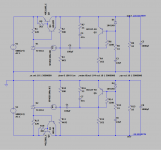
Negative regulator with TL431
Positive regulator based on the TL431 voltage reference is supplemented with true symmetrical negative. Circuit shown is targeted at voltage regulator for amplifiers or high current at minimal voltage drop. It’s working at only 1,5 V drop across the regulator and still maintaining over 100 dB PSRR. That provides ripple in the range of microvolts. Noise level is ridiculously low at 0,1 uV and output impedance is less than 1 mΩ in the whole audio band and up to 1 MHz.
With more input to output voltage difference, it’s easy to get 20 dB more, and with CCS instead R1/R17 another 20 to 30 dB.
Circuit is stable up to unrealistically low 2 mΩ ESR of output capacitor.
I will go in the direction of building small add on modules that can be used instead of resistor in the any CRC power supply, thus greatly enhancing their characteristics. This is in line with original idea of denoiser circuit and it is the most useful one I can picture.
Attachments
The negative regulator doesn't work correctly.
The load regulation is not correct because the Vbe of Q1 comes in the regulation loop.
With this schematic we have.
Vout- = - ( 2.5V - Vbe )*( 1 + R10/ R11 )
Load regulation is lost because it is modulated by the load current.
The positive regulator works fine.
Vout+ = 2.5V *( 1 + R2/R3 )
The load regulation is not correct because the Vbe of Q1 comes in the regulation loop.
With this schematic we have.
Vout- = - ( 2.5V - Vbe )*( 1 + R10/ R11 )
Load regulation is lost because it is modulated by the load current.
The positive regulator works fine.
Vout+ = 2.5V *( 1 + R2/R3 )
A better way about the negative regulator is to have R11 at the anode of TL431 instead of out-.
Vbe comes in the Vout- equation but not as bad.
This is using the TL431 as a zener diode programmed by R10/R11. The load regulation stays poor, not as good as the positive regulator.
This gives:
Vout- = -2.5V * ( 1 + R10/ R11' ) + Vbe
Vbe comes in the Vout- equation but not as bad.
This is using the TL431 as a zener diode programmed by R10/R11. The load regulation stays poor, not as good as the positive regulator.
This gives:
Vout- = -2.5V * ( 1 + R10/ R11' ) + Vbe
Last edited:
OK, I think I've read the whole thread now, some parts several times, and this is all above my pay grade, so please bear with.
I'm looking for a power supply solution for a desktop build of xrk971's PCA. It eats ~150mA@18v.
My pocket variant has a capacitance multiplier and a CRCRC (2200uF/.47ohm) before the amp - neither of these are no longer needed, right? This solution takes care of soft start too? There are also a pair of 2200uF rail caps on board.
I'm going to be using some sort of repurposed brick for AC-DC, so I'm guessing I should be looking at the OG Denoiser circuit? Kind of looking for the solution with the smallest part count/footprint/complexity and going to lay it down on a PCB protoboard.
If I take a 30V brick I will need some sort of "preregulator" to take an initial power dissipation hit, maybe another 317 (I also seen someone mention BD00C0AWCP) - this won't cause an issue?
I don't believe I have BC337-40 (or any of the other BJTs I've seen mentioned) but I do have BC337-25 - is the difference significant for this application?
Thanks
I recommend that you just use Sadface's circuit, page 52, post #518:
D-Noizator: a magic active noise canceller to retrofit & upgrade any 317-based V.Reg.
It works, uses the LM317/337 with Elvee's denoiser and has GREAT heat sinks as well. I believe it lowers any power supply-induced artifacts to inaudible levels and will deliver up to 2 amps of power to whatever ya have. He's graciously provided the Gerbers so you can order boards straight from jclpcb. I made up a bunch and I think they cost me less than $20 apiece including boards and parts. You'd be hard-pressed to beat that!
Last edited:
Yes, there is no easy way to make negative regulator with TL431 that works as intended in every aspect. Load regulation on the negative regulator is deteriorated but dynamic advantages of denoiser circuit are there: PSRR, noise, dynamic impedance. If load current of negative regulator is changed by couple of A, output voltage changes in tenths of volt range.
If R11 is moved to the TL431 anode, voltage reference of TL431 is moved outside regulation loop and all benefits of the denoiser circuit are lost.
I see this good enough for the class A amplifier PS, where there is no regulation at all or capacitance multiplier is used at best. Cap MX has no load regulation and worse PSRR and noise figures.
I’m not finished with this jet and will try to find acceptable solution for negative regulator that maintains load regulation.
Thanks but I don't need 2 rails and that's a lot more physical room than I have to work with - I plan on throwing the DC-DC into the little ~7*2*12 aluminum enclosure and also potentially use it for heatsinking, frankensteining an additional heatsink as the back panel if that turns out insufficient. Am also looking to crank this out tomorrow (long shot) with what I have on hand.I recommend that you just use Sadface's circuit, page 52, post #518:
Thanks but I don't need 2 rails and that's a lot more physical room than I have to work with - I plan on throwing the DC-DC into the little ~7*2*12 aluminum enclosure and also potentially use it for heatsinking, frankensteining an additional heatsink as the back panel if that turns out insufficient. Am also looking to crank this out tomorrow (long shot) with what I have on hand.
The denoiser in the 1st post should work fine and is fairly easy to put on a protoboard. You can add an RC prefilter to drop some volts if your DC-brick outputs 30 V and your target is 18V. You can use your existing BC337-25.
I do not agree.If R11 is moved to the TL431 anode, voltage reference of TL431 is moved outside regulation loop and all benefits of the denoiser circuit are lost.
The PSRR improvement from the denoiser circuit is effective.
- Home
- Amplifiers
- Power Supplies
- D-Noizator: a magic active noise canceller to retrofit & upgrade any 317-based V.Reg.