@tombo56 can you generously provide 5v and 3.3v BOM too? Are you working on 15V analog version specifically?
There are more details here for resistor values:
https://www.diyaudio.com/forums/pow...fit-upgrade-317-based-reg-11.html#post6054925
Also referencing this post:
https://www.diyaudio.com/forums/pow...ofit-upgrade-317-based-reg-9.html#post6021955
Last edited:
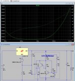
Here are the values that simulation predicts to be good for the 3,3V output. It is roughly the same for 5V, except R2 value.
The regulator you used was the Dienoiser.
I got slightly better psrr results on the curve. Probably the 317 model I'm using.
Attachments
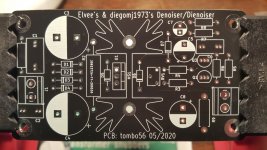
I can provide the single rail version (LM317) with Sziklai transistors pair, in this thread referenced as dienoiser. PCB uses both copper sides, for low impedance, and has proper Kelvin connection. There are positions for snubber parts as is hard to expect maximum performance without it. ATM, it is untested as well. I have ordered PCBs at last Friday from JLCPCB, but won’t assemble any immediately. Only after several weeks I could confirm if everything is in order with the design. If there is an interest or urgent need, let me know an I will attach gerbers if you are willing to try. PCB dimensions are 50 x 90 mm.
What is the minimum load draw required? LM317 base-spec is 5mA. Just scratching my head about R9.
Just the base and the collector resistors, but there is only 1 ~ 2dB to be gainedYou mean all resistors in circuit? I think most of people here planing to use single rail de/dienoiser on their DAC projects like myself. It seems we need confirmed values (or complete circuit diagram) for 5v and 3.3v versions.
I do not see anything abnormal in the layout. It could be your particular regulators, but the circuit has been tested and used with regulators of many different sources, and many of my tests were made on a breadboard, thus a much lower standard than your PCBSo, I scaled down the voltage to around 32V and still have the same problem, the voltage rises under load. The problem should not immediately be connected to the higher output then. I need a negative version, and alternative regulators and the HV type are not applicable to the negative rail. Or is there anyone I don‘t know?
Indeed there is oscillation at the collector of the transistor, around 400mV p2p at 12kHz. Thanks for the tip. It was not really visible at the output, there it was only around 4mV. (I used 1:10 probes so it was only barely visible 400uV at the output)
For the layout, I used the pcbs that I showed earlier in this thread:456
I will check layout and solder work for anything suspicious.
Thanks for the help.")
What is the minimum load draw required? LM317 base-spec is 5mA. Just scratching my head about R9.
R9 depends on the output voltage and needed minimum load current. Take in the account that several mA passes through voltage divider (R3, R4, RV1). It is safe to put 1 K to 1,2 K for every 10V on the output. So, for 20 V output, R9 = 2,2 to 2,7K. It’s not that critical.
The regulator you used was the Dienoiser.
I got slightly better psrr results on the curve. Probably the 317 model I'm using.
Yes, I agree that it is possible to get better results. It was just ballpark simulation.
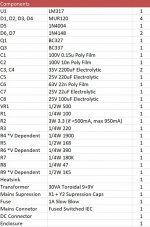
Preliminary BOM for adjustable 12.1 - 15.0V on Tombo56 Single Rail Board Here
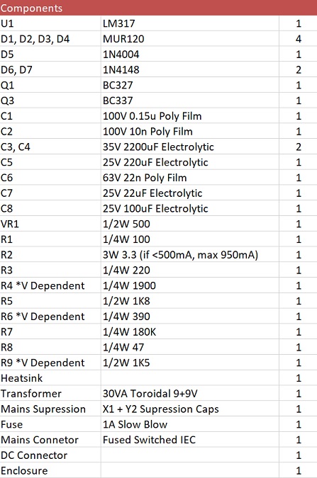
Resistor tolerances very conservative. R5 is 1/2W to allow for 24-30V. R2 3W gets you to 950mA before burning. I haven't measured your lead or radial spacing so haven't exactly matched specific components, yet. Will post the full BOM when ready.
Other voltages
- Change capacitor tolerances, R4, R6, R9, and transformer.
- R4, R6, VR1: For quick reference visit https://www.diyaudio.com/forums/pow...fit-upgrade-317-based-reg-11.html#post6054925
- R9 dependent on voltage, to maintain constant current draw of 5-10mA. Classic equation of R9=V/0.01
Notes
- R1 can be fine-tuned for specific transformer, but 100ohms is a good start. See Simple, no-math transformer snubber using Quasimodo test-jig
- VR1 is also optional if you want fixed voltage (requires jumper).
- Add in some mains suppression X/Y caps.
Attachments
Yes, EXACTLY! The fun and flexibility of being able to greatly improve an existing regulator is key. It can also be quite a challenge to shoe-horn it in on your existing boards. I KNOW this quite well!The fun or practicality in using the Denoiser or Dienoiser with 3X7 regulators is that you may already have some or you can get them quite cheap from eBay, with little chances of the regulator chip being fake, I believe........You can take (or should prefer) a non assembled 317/337 regulator kit such as this, add two Denoiser/Dienoiser piggbacks, and end up with a top regulator, comparable to the best around, including Jung's superregulator.
Preliminary BOM for adjustable 12.1 - 15.0V on Tombo56 Single Rail Board Here

Resistor tolerances very conservative. R5 is 1/2W to allow for 24-30V. R2 3W gets you to 950mA before burning. I haven't measured your lead or radial spacing so haven't exactly matched specific components, yet. Will post the full BOM when ready.
Other voltages
- Change capacitor tolerances, R4, R6, R9, and transformer.
- R4, R6, VR1: For quick reference visit https://www.diyaudio.com/forums/pow...fit-upgrade-317-based-reg-11.html#post6054925
- R9 dependent on voltage, to maintain constant current draw of 5-10mA. Classic equation of R9=V/0.01
Notes
- R1 can be fine-tuned for specific transformer, but 100ohms is a good start. See Simple, no-math transformer snubber using Quasimodo test-jig
- VR1 is also optional if you want fixed voltage (requires jumper).
- Add in some mains suppression X/Y caps.
This project was tailored to my specific needs and, becoming public, it needs some adjustments depending on output voltage and load current. This is well enough covered in this very good BOM list but some additional comments are needed.
For lower voltages, C3 & C4 can be of a bigger capacity, available up to 10.000 uF in the 16 mm diameter envelope. I will use 3.300 uF/25V.
C5, C7, C8 will likely need to be 50V variants to find ones with pitch 5 mm and 2,5 mm.
R2 should be 1 to 2,2 ohm or, depending on load current I would keep 1 V voltage drop across it. My intended use is low current, hence this high value on the schematic.
Heatsink is Fischer SK129 series with length from 25 mm to 50 mm
PCBs arrived yesterday. I hope that I will be able to confirm design working till next Thursday.
Attachments
Kumori, what type of 10n cap do you use? It looks suspiciously large for such a small, low voltage cap.
It is a Wima FKP2 10nF. Is this too „boutique“?
I‘ll see if I have a suitable X7R type to swap.Haha, the FKP2 might be the wrong capacitor in this application. I just doubled the capacitance via flying leads. This doubled the oscillation amplitude. Then I thought: what about no capacitance? Removed the cap and the oscillation is gone.
The output voltage is stable now at 30V and 50V, at least up to 20 mA.
Are ceramic types really necessary in this position? How is this to be interpreted?
The output voltage is stable now at 30V and 50V, at least up to 20 mA.
Are ceramic types really necessary in this position? How is this to be interpreted?
I am not completely sure, but FKP caps are tuning capacitors, meaning their self inductance does not matter very much (up to a point).
Unlike extended foil types, they have one or two connection points to the foil, and this means that their HF bypassing capability is limited.
A ceramic disc or MLCC is quite sufficient for this job, and doesn't have this kind of issue.
The circuit might be stable with no cap at all, but I do not recommend it as a final solution: there will be some HF peak in the FR
This project was tailored to my specific needs and, becoming public, it needs some adjustments depending on output voltage and load current. This is well enough covered in this very good BOM list but some additional comments are needed.
For lower voltages, C3 & C4 can be of a bigger capacity, available up to 10.000 uF in the 16 mm diameter envelope. I will use 3.300 uF/25V.
C5, C7, C8 will likely need to be 50V variants to find ones with pitch 5 mm and 2,5 mm.
R2 should be 1 to 2,2 ohm or, depending on load current I would keep 1 V voltage drop across it. My intended use is low current, hence this high value on the schematic.
Heatsink is Fischer SK129 series with length from 25 mm to 50 mm
PCBs arrived yesterday. I hope that I will be able to confirm design working till next Thursday.
Thanks for the additional comments Tombo. Sorry, didn't have time to measure the Gerber lead spacing yet, so this is very helpful. Hopefully everything is covered now
I didn't want to get into tweaking the pi-filter too much, but yes increasing the capacitance is preferable. However, for same reason, so would keeping R2 reasonably high? (with a higher power rating sacrifice). A cut off around 5-10Hz seems reasonable? (a bit off topic, sorry LV)
I can provide the single rail version (LM317) with Sziklai transistors pair, in this thread referenced as dienoiser. PCB uses both copper sides, for low impedance, and has proper Kelvin connection. There are positions for snubber parts as is hard to expect maximum performance without it. ATM, it is untested as well. I have ordered PCBs at last Friday from JLCPCB, but won’t assemble any immediately. Only after several weeks I could confirm if everything is in order with the design. If there is an interest or urgent need, let me know an I will attach gerbers if you are willing to try. PCB dimensions are 50 x 90 mm.
Just a quick thought, sorry if I'm wrong but just wanted to double check. I was looking at my Eagle libraries. I'm trying to design something with transformer on board, and will release some details soon.
Is BC337 pinout incorrect in the default library? Datasheet says CBE:
1 - Collect
2 - Base
3 - Emitter
However, Eagle and your board seems to be configured for EBC.
Seems like a common problem: https://www.element14.com/community...ut-editor-pnp-transistor-e-and-c-pins-swapped
If so, obviously not a huge deal, just need to mirror the transistor upon assembly.
Last edited:
I am assembling my Sadface-layout regulator boards. One small omission I see is that the 33Ω resistor that is recommended (in series with the 10-15nF comp cap) for the LM337 negative side is NOT there. I think I can sandwich it in there anyway. I would also have preferred that the input side (from the transformer secondary windings) be made to accommodate the normal 3-pin, 5 mm screw terminal blocks. As is, I'll have to use three 2-pin ones---no biggie.
I am assembling my Sadface-layout regulator boards. One small omission I see is that the 33Ω resistor that is recommended (in series with the 10-15nF comp cap) for the LM337 negative side is NOT there. I think I can sandwich it in there anyway. I would also have preferred that the input side (from the transformer secondary windings) be made to accommodate the normal 3-pin, 5 mm screw terminal blocks. As is, I'll have to use three 2-pin ones---no biggie.
That's quite a glaring omission on my behalf. I haven't updated the basic schematic from way back on something like page 25.
I will have to dig through the thread and find the change.
I did fix the issue with the screw terminal blocks on my recent version 2.0.
It looks like I need to do a version 3.0.....
Last edited:
Is BC337 pinout incorrect in the default library? Datasheet says CBE:
1 - Collect
2 - Base
3 - Emitter
However, Eagle and your board seems to be configured for EBC.
It’s morning and not enough coffee circulating my blood stream
but BC337 pads seems to be right. Pin 1 is collector and it is connected to the R6. Pin 3 emitter is connected to the ground.As for R2, there is no place for higher power rating resistor. I will use 2W. RC filter is not primary for increasing PSSR at 100 Hz but for maintaining good PSSR at higher frequencies, thus filtering HF noise from rectifier and mains.
One additional note: MUR 120 diodes are good up to 300 – 400 mA load. For higher current I would use SBYV27-200 diodes.
- Home
- Amplifiers
- Power Supplies
- D-Noizator: a magic active noise canceller to retrofit & upgrade any 317-based V.Reg.