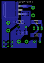
Your pics are too small to be interpreted at a glance: it is difficult to see where the pads connect with the copper pour, but as a general rule a star-like configuration is preferable.
Ground planes can be useful for Faraday shields, microstrips and other specific purposes, but not to control the path of currents in a board.
If you follow the general outline of the schematics, in particular that of the nonoiser with Kelvin connections, you are on the right track even if you do not use actual Kelvin connections.
Thanks for the help. The pictures are indeed a bit small.
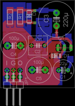
I attached larger pics with topside as groundplane and two different star-ish arrangements.
The largest current flux to GND is from the input cap C4, that shold be put furthermost upstream, but since all grounds join anywhere within close proximity it is probably academic.
Q1 is routed directly to the output cap C5 in the non-groundplane versions, as in the Nonoiser. Should all other ground ideally also meet at C5 in the Denoiser?
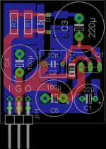
Attachments
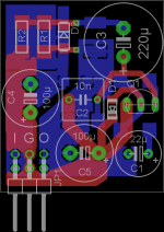
Yes, it is preferable: this version is probably the best you can achieve with three terminals:Q1 is routed directly to the output cap C5 in the non-groundplane versions, as in the Nonoiser. Should all other ground ideally also meet at C5 in the Denoiser?
") .
.
If you're going to include a filter at all, why not set its cutoff frequency to 3 Hz or lower? What's great about "flatter but higher" rather than "sloping but lower" ?Dienoiser tip: incorporating a first-order RC filter with a cutoff frequency between 50 to 100 Hz prior to the voltage regulator
Setting a cut-off frequency of less than 3 Hz instead of 50 to 100 Hz in a first-order filter, implies using a capacitor with a value more than 33 times higher than the current one, since we are talking about placing it before the input of the regulator. As the output current must circulate through the series resistor, that same resistor must be of relatively small value (at most 1 ohm or less, depending on the output current and the allowable voltage drop). If you make your calculations, a 2200 uF capacitor with a resistor of 1 ohm meets the curve shown, but if you set 3 Hz the capacitor becomes as large as 53051 uF !!!.
In addition, there is no need for greater attenuation at higher frequencies, since the amplitude of the spectral components of the noise are generally decreasing with the frequency.
Best regards
In addition, there is no need for greater attenuation at higher frequencies, since the amplitude of the spectral components of the noise are generally decreasing with the frequency.
Best regards
Attachments
Last edited:
I did some measurements which I an happy to share with this community. But first let me show you the schematic I worked from. It is the Diego enhanced version of the denoizer that Elvee invented. I built both a 337 and a 117 version.

The effect on noise is quite remarkable. I have done tests with all kinds of shunt and other regulators, but this is an entirely different ballgame.
The effect on noise is quite remarkable. I have done tests with all kinds of shunt and other regulators, but this is an entirely different ballgame.
But first let me address the following: I don't think the LTSpice sims work like everybody thinks. Try this:

The connection between Q6 and C10/12 has been cut. However, it sims just like the version with the connection made. Wierd. The only thing I can come up with is that the network can also work as a shunt between the two power lines, and that this is what the sims show.
However, in my test fixture, cutting this connection has a huge effect.
So, my question to y'all is: did I do something wrong here, and if not, what is going on?
View attachment 806095
This is the test fixture I have been doing measurements on. There is a positive and a negative side. In both, by adjusting jumpers, the denoizer can be switched on or off, or the 220 uF cap over R14 can be switched to ground or be lifted. After the denoizers, I built a roughly 1000x times amp from an LME49990. Noise levels of even a bare LM117 are too low to be shown direcly on a scope or be measured with a volt meter (at least, the ones I have).
For those who want to do some sims to find out where I might have gone wrong, here is the spice file. I would love to have a model for the LM337, but the one I found on the net doesn't seem to work. As long as I don't think it sims properly anyway, that point is moot.
View attachment 806099
Last edited:


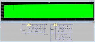
With the denoizer on, the noise climbs to .12 uV, but it must be even lower in a well shielded setup. I can see the sort of variations in the noise voltages, .12 was the maximum. And it reacts to presence of a hand or finger like a Theramin, it is very sensitive to EMI. In short, shielding will be important to get the best results.


I am building a sweepable powersource, in which I can superimpose dirt on top of the DC voltage. Let's see how we fare with PSRR. I will also do some stability tests and will try to sweep Zout. But first we have to solder on.
Edit: for good order, I am using BC549/560C low noise transistors, since that is what I had laying around.
Edit: for good order, I am using BC549/560C low noise transistors, since that is what I had laying around.
Last edited:
Vacuphile,
Please upload the asc file, as your uploading failed.
One problem I have had with Diego's regulators sim was with the transient response. Did you run it on your sims?
Why do you consider the LT3042 as your noise reference? Isn't Jung-Didden noise better than the 3042?
What about the noise from Elvee's Denoisator and NoNoiser?
Hi Calmart,
Hope it works now
View attachment D_noisatorDi +-streamline.asc
As to your other questions: yes, from what I have seen up till now, it is better. However, it may all come down in flames after doing the other tests, will have to find out. As to the sims, I don't think they really work like the real thing, see the above.
Before that question comes up: the tests were done loaded with 110 Ohm.
Last edited:
- Home
- Amplifiers
- Power Supplies
- D-Noizator: a magic active noise canceller to retrofit & upgrade any 317-based V.Reg.