They should not be distracted by breathing. Should concentrate on doing their job.Yeah, but then the electrons cain't "breathe"!
Drawing a circuit in such a nonsensical way is asking for trouble.
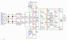
Despite the simplicity, I managed to spot two errors (there might still be one or two hiding in plain sight)

Edit: yes in fact, C13 and C14 should connect to GND, they are drawn just in series
Despite the simplicity, I managed to spot two errors (there might still be one or two hiding in plain sight)
Edit: yes in fact, C13 and C14 should connect to GND, they are drawn just in series
Attachments
Last edited:
Thanks for the feedback guys.
The layout is a bit messier than I would like compared to drawing by hand, but that is unfortunately the limitations of the easyEDA software. I can't rotate Q1 to make the connection to the base clearer without having to fiddle around with everything else so I opted to run the link through the middle.
I am little embarrassed at missing link from C9 to Q1 and the missing links to ground on C13 and c14. I'm going to claim it was late and leave it there....
Thanks for spotting that Q2 was around the wrong way also.
I did consider using 2x LM317 but that adds some complexity to the grounding whereas by using the LM337 I can use a nice simple ground bus straight through the middle of the board like a standard implementation bipolar board.
Here is the corrected version.

I do have a question as to whether the CRC filter before the regs is necessary with the denoiser afterwards.
Just in case anybody is wondering, the paralled resistors at R5 and R6 is to facilitate odd resistor values. In this case for 15v out one needs a 1.1k resistor in r5 and r6 which is uncommon compared to parallel 2.2k.
From earlier in the thread I understand r7 and r8 are optional but potentially improve stability so I figured I may as well leave them in there.
What am I missing? There's no connection to the base of the transistors Q1 & Q2.
The layout is a bit messier than I would like compared to drawing by hand, but that is unfortunately the limitations of the easyEDA software. I can't rotate Q1 to make the connection to the base clearer without having to fiddle around with everything else so I opted to run the link through the middle.
Drawing a circuit in such a nonsensical way is asking for trouble.
Despite the simplicity, I managed to spot two errors (there might still be one or two hiding in plain sight)
Edit: yes in fact, C13 and C14 should connect to GND, they are drawn just in series
I am little embarrassed at missing link from C9 to Q1 and the missing links to ground on C13 and c14. I'm going to claim it was late and leave it there....
Thanks for spotting that Q2 was around the wrong way also.
... besides .... I would rather use 2 x LT317 instead of LT317 + LT337.
The LT337 has somewhat inferior noise figures.
Gimmick would require some serious rewiring though.
I did consider using 2x LM317 but that adds some complexity to the grounding whereas by using the LM337 I can use a nice simple ground bus straight through the middle of the board like a standard implementation bipolar board.
Here is the corrected version.
I do have a question as to whether the CRC filter before the regs is necessary with the denoiser afterwards.
Just in case anybody is wondering, the paralled resistors at R5 and R6 is to facilitate odd resistor values. In this case for 15v out one needs a 1.1k resistor in r5 and r6 which is uncommon compared to parallel 2.2k.
From earlier in the thread I understand r7 and r8 are optional but potentially improve stability so I figured I may as well leave them in there.
From earlier in the thread I understand r7 and r8 are optional but potentially improve stability so I figured I may as well leave them in there.
LV's Post 201 :
R3 (the 33 ohm) can improve stability, when the 317 implementation is non-standard, or if you want to try other types of regulators.
It also makes the circuit more forgiving of layout blunders.
It is unnecessary when used with a plain-vanilla 317 circuit (but it will do no harm)
"can improve stability" .... but doesn't say what stability , ac or dc stability , or oscillating if used without the 33 ohm ?
My LM+DeNoiser will be on a 14x14 mm PCB , so not much chance of layout blunders.
"plain-vanilla 317 circuit" ... not sure what LV means here. Once you use the DeNoiser , the 317 stops being a plain vanilla circuit.
D10 's cathode to the ground , anode to the base.
Last edited:
You may want to have a look at an alternative tool: DipTrace.... but that is unfortunately the limitations of the easyEDA software. I can't rotate Q1 to make the connection to the base clearer without having to fiddle around with everything else ...
It is free of charge for up to 300 pins (500 pins with educational licence).
It is actually a commercial product, but free for use with full functionality up to said 300 pins.
Download DipTrace - DipTrace
DipTrace - Schematic and PCB Design Software
Film with tutorial / first impressions:
YouTube
Last edited:
I would say yes, it is necessary. To decrease the amount of ripple, so that the 317/337 can operate properly. The regs have a minimum dropout that needs to be ensured, for them to operate properly. My gut feeling would be 1,5...2,0 to keep me and the regs happy.I do have a question as to whether the CRC filter before the regs is necessary with the denoiser afterwards.[/FONT]
But there is a catch here. If you consider ripple voltage as an AC voltage superimposed on the DC that comes from the rectifier, you will also appreciate that there is a Vmax and Vmin within that input voltage.
With increasing load current, the ripple, or difference between Vmax and Vmin increases, because Vmin gets lower and lower.
If Vmin is sufficiently low, there will be moments during the cycle where the dropout that is necessary for correct operation of 317 / 337 is not maintained, and the 317 / 337 will fall out of regulation. The regs will simply not have enough overhead, or dropout voltage, to 'work on'. Hence, there will be times of the cycle during which they will not do their work properly.
That is the reason that you need some preliminary, and sufficient for the job, pre-filtering, just to keep the ripple within reasonable values.
There is even a formula that will allow you to assess the amount of ripple (Vmax-Vmin) that results from pulling a given load current from a filter capacitor of a given capacity uF. You need to dig it up and to the maths. Based on that, on the Vout, and the anticipated load current, you will have a gut feeling as to the magnitude of the ripple that is to be anticipated. You can then scale up or down the uF of the filtering capacitors and then assess the AC voltage that you need on your secondary to power up this thing.
Last edited:
33 ohms: Correct me if I am wrong, but the 33 ohms introduces additional damping so as to WORSEN the ESR parameters of the capacitor it is in series with. This is done on purpose, so as to alleviate the risk of ac instability, ringing, or possibly even self oscillation of the circuit,
which according to my gut feeling could vaguely resemble a Wien Bridge / oscillator. (???)
Introducing damping to the capacitor ensures that any tendency do ring or oscillation will be swamped.
I believe. Not sure.
which according to my gut feeling could vaguely resemble a Wien Bridge / oscillator. (???)
Introducing damping to the capacitor ensures that any tendency do ring or oscillation will be swamped.
I believe. Not sure.
Last edited:
... the connector P5 suggests that you want to use three wires: Plus, Ground and Minus.
...
Maybe it would be worth considering to expand the P5 connector with two additional signals: Sense_Return_Positive and Sense_Return_Negative.
As in the case of any three legged and ground referenced regulator, I suspect that the NoNoiser can be also used in a half-sensing mode, with voltage sensor on the ground returns. A change would be required in the design and wiring of the board, so as to implement such strategy (Current_Plus, Sense_Return_Positive, Ground, Sense_Return_Negative, Current_Minus).
Last edited:
My guess is that in order to implement such half-sensoring, the legs of R5 and emitter node of Q1 would need be disconnected from local NoNoiser ground and routed out as a "Positive_Sense_Return" signal for the upper side.
Similarly, the legs of R6 and emitter node of Q2 would need be disconnected from local NoNoiser ground and routed out as a "Negative_Sense_Return" signal for the lower side.
At the remote load, the Ground would be connected with the Negative_Sense_Return and with the Positive_Sense_Return. Appropriate wiring would need to be maintained, and stability issues would need to be considered in such a scenario.
Benefit of such a 5 wire solution would be that the sensing would circumvent any and all voltage dropouts on the joint ground return current lead, as the sensing would be done on the pins of the actual load, rather than locally within the NoNoiser.
Unfortunately, it is NOT possible to do full sensing on three-legged-based regulators for the other current carrying wire(s). But half sensing does improve things a bit.
Last edited:
LV's Post 201 :
R3 (the 33 ohm) can improve stability, when the 317 implementation is non-standard, or if you want to try other types of regulators.
It also makes the circuit more forgiving of layout blunders.
It is unnecessary when used with a plain-vanilla 317 circuit (but it will do no harm)
"can improve stability" .... but doesn't say what stability , ac or dc stability , or oscillating if used without the 33 ohm ?
My LM+DeNoiser will be on a 14x14 mm PCB , so not much chance of layout blunders.
"plain-vanilla 317 circuit" ... not sure what LV means here. Once you use the DeNoiser , the 317 stops being a plain vanilla circuit.
D10 's cathode to the ground , anode to the base.
D10 needs to be reversed.
... the connector P5 suggests that you want to use three wires. As in for Plus, Ground and Minus.
...
Maybe it would be worth considering to expand the P5 connector with two additional signals: Sense_Return_Positive and Sense_Return_Negative.
As in the case of any three legged and ground referenced regulator, I suspect that the NoNoiser can be also used in a half-sensing mode, with voltage sensor on the ground returns. A change would be required in the design and wiring of the board, so as to implement such strategy (Current_Plus, Sense_Return_Positive, Ground, Sense_Return_Negative, Current_Minus).
Thanks guys, I appreciate the feedback.
I thought that d10 looked wrong during pcb layout.
At this point in time the kelvin connections are a bit beyond my understanding so I'll omit that strategy at this stage.
I've decided that spade connectors for the AC connections were going to take up too much space. I've changed to a 3 pin screw terminal block for AC connections. I did however decide to add a spade terminal for the main earth connection to chassis.
Some other design decisions include: 18mm diameter,7.5mm pitch caps for c1-c4 with some additional 5.008mm pitch pads so as to accommodate a wide array of filter caps. I would like this board to be able to be used with whatever is lying around rather than being boxed into certain part choices due to size constraints.
Apart from R1 which is sized for 1w resistors, the rest of the resistors are sized for 1/8 watt. I am reconsidering changing to .25w or .5w for flexibility.
I've chosen to pack the components tightly around the regs to save space at the expense of not accommodating larger heatsink types.
I am also reconsidering the size of caps to allow for the rest of the electrolytics. Currently their all sized for 10mm diameter, 3.5mm pitch but this seems a bit large for the smaller values.
Here's my working schematic:

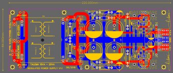
Here's my PCB first draft:

It may be worth considering to rearrange the 317 / 337 positioning on the PCB Layout?
In such a manner, so that their hot backs are aligned with the sides of the PCB board.
This way, depending on application, you have the option of mounting the 317 / 337 to some optional heatsinks, on the sides of the board, and you will not be constrained by the other elements on the PCB that exist in the vicinity of the regulators.
The 317 / 337 could be positioned slightly indented, such that there is still some slack on the sides of the board, to accomodate "on-board" a small heatsink, mounted directly on the PCB, or so that the 317 / 337 could be bent-out towards the rim of the PCB and mounted to a wholly off-board set of heatsinks.
Just an idea.
Considering, that such a circuit could be possibly used with load currents of even up to 1,5A, times a dropout voltage of say 2V, that would result in some serious heat dissipation, 3 Watts. Or even more.
In such a scenario, a heat sink seems to be essential.
Last edited:
YES YOU CAN.....use the flip horizontalThe layout is a bit messier than I would like compared to drawing by hand, but that is unfortunately the limitations of the easyEDA software. I can't rotate Q1 to make the connection to the base clearer without having to fiddle around with everything else so I opted to run the link through the middle.
Attachments
The reduction to 100 ohm of R3 R4 will very marginally improve the DC stability, but below the datasheet recommended value of 240 ohm, you get diminishing returns.
The quiescent dissipation will be doubled, and the Denoiser will lose ~6dB of correction efficacy, because of the lower impedance.
The poles caused by C7 C8 will move higher in frequency, meaning a less extended VLF response, and a stronger bump in the response as they will be closer to the input ones.
Nothing catastrophic, sure.
With this implementation, R7 and R8 are unnecessary, and can be strapped or left in place
YES YOU CAN.....use the flip horizontal
Thank you.
SadFace you should take this drawing without the transformer as an example i posted it in the P88 thread to help you
Upon close inspection, that is quite a tidy layout. I borrowed some ideas.
I've gone back to spade connectors for the transformer connections as I ended up having the space and I much prefer them to screw terminals in this application. I've changed the resistors to 1/2 watt sizing for flexibility.
And of course I added heatsinks.
I was previously planning to use the smaller type that hang off of the reg and don't require pcb space. However upon further consideration these were going to foul on c7 and c8. So I will take the advice to add the footprint for a heatsink. I chose to make the board wider rather than longer which allowed me to fit a large fan type footprint. I couldn't find an implementation with the heatsink aligned with the edge that didn't add excess dimensions so I've gone with a north south orientation. I've managed to shave a 10mm off the length but width has gone up 30mm overall due to the heatsinks.
The reduction to 100 ohm of R3 R4 will very marginally improve the DC stability, but below the datasheet recommended value of 240 ohm, you get diminishing returns.
The quiescent dissipation will be doubled, and the Denoiser will lose ~6dB of correction efficacy, because of the lower impedance.
The poles caused by C7 C8 will move higher in frequency, meaning a less extended VLF response, and a stronger bump in the response as they will be closer to the input ones.
Nothing catastrophic, sure.
With this implementation, R7 and R8 are unnecessary, and can be strapped or left in place
I've removed R7 and R8. I've changed r3 and r4 back to 240R and changed R5 and R6 to a 5k trimpot for simplicity.
Here's the corrected schematic

Here's the current PCB draft


Be aware that R5 & R6 need to be the cream of the cream: generally, trimmers are noisy, unstable, non-linear but it does not matter when they are ~10% of the total resistance.and changed R5 and R6 to a 5k trimpot for simplicity.
Here's the corrected schematic
View attachment 790726
Here's the current PCB draft
View attachment 790727 View attachment 790728
Here they are 100%.
When possible, connection in potentiometer mode improves matters, but with the 317, it is not possible
Easy to evaluate:Nice work!!
I usually use a 10,000µF cap as a smoother after the rectifier----does the 2 x 2,200µF + 10Ω resistor perform better than this?
The 2200µ solution will start with a ripple ~4.5 times the 10,000µ.
At 100Hz the reactance of a 2200µ is 0.7ohm, and will divide the input ripple by ~10/.7=14.
As the initial ripple was 4.5x larger, the final gain with the CRC will be 14/4.5=3.1
So, it's better, but if you use it at 1A, it will generate a lot of heat....
- Home
- Amplifiers
- Power Supplies
- D-Noizator: a magic active noise canceller to retrofit & upgrade any 317-based V.Reg.