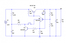
This PSU handles a number of functions for battery-operated devices:
It is basically a LDO regulator, but it also performs the ON/OFF function with a single push-button, the power indication, lo-bat indication and short-circuit protection.
It is absolutely minimalistic, comprising only 2 discrete transistors.
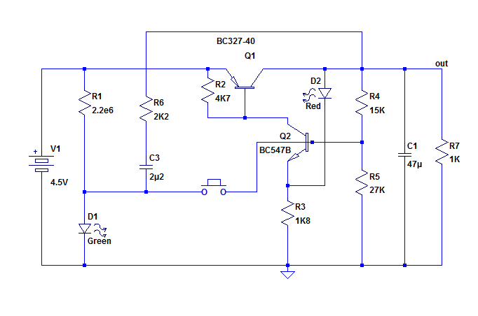
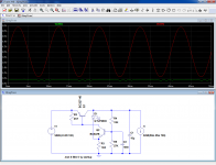
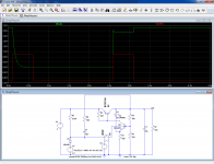
This pic shows the core of the circuit subjected to simultaneous input and load ripple:

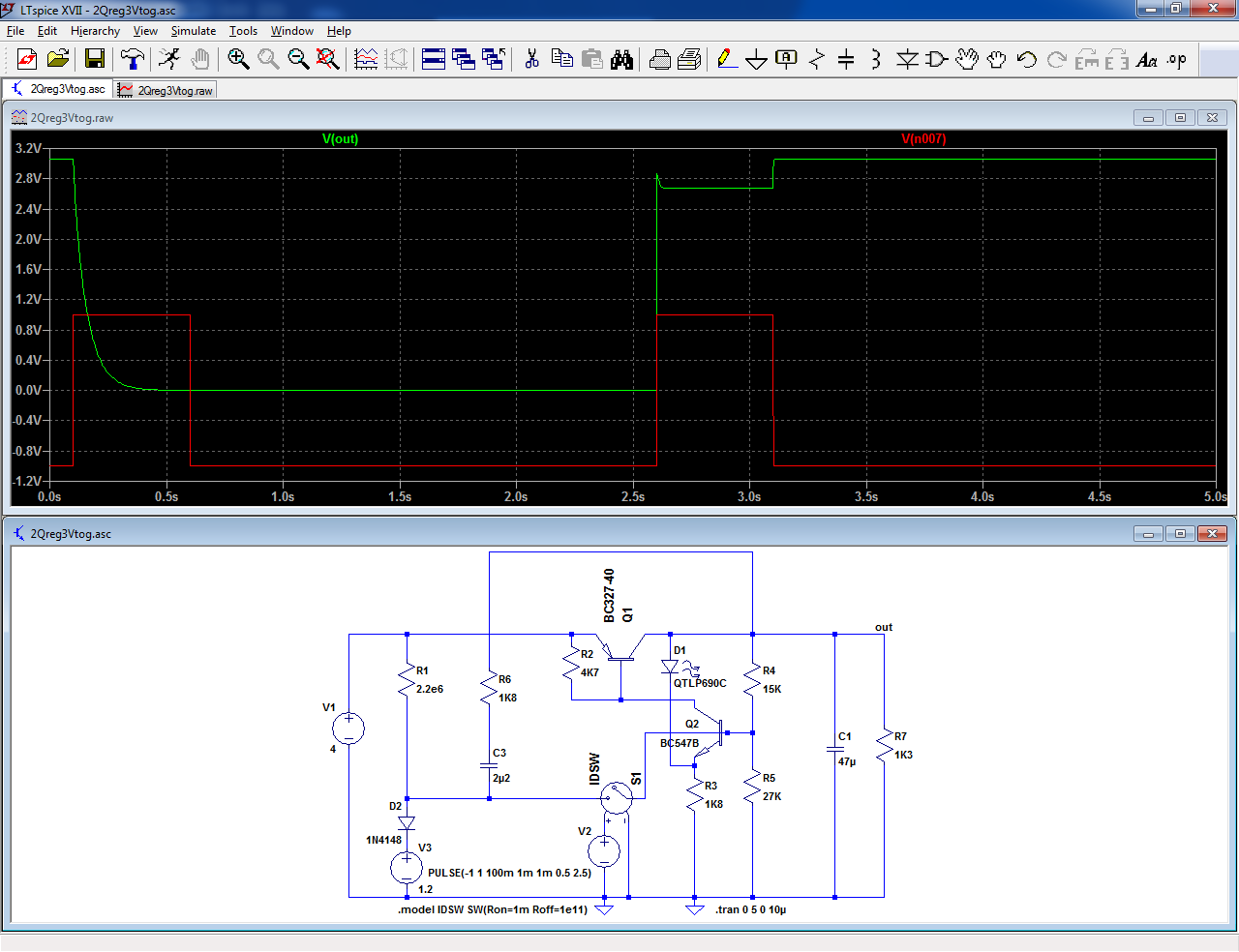
To create the toggle function, a few components are added:
When the circuit is off, the current consumption is ~1µA.
The component values are suited for an output current of 50~100mA, but by scaling the resistors values, any value can be obtained: multiply them 100 times, and you have a micropower regulator.
The reference voltage is generated by the red LED: its tempco compensates the Vbe of the transistor.
This LED also serves as a power indicator (use a low-current type), and as a lo-bat indicator: when the battery voltage is too low, Q2 steals all the available current for Q1's base.
The circuit is short-circuit protected because it is based on regenerative action: if the output current exceeds Q1's capability, the circuit trips and turns off, and cannot be turned on again until the short has been removed.
The following pic illustrates the toggle operation:
It is basically a LDO regulator, but it also performs the ON/OFF function with a single push-button, the power indication, lo-bat indication and short-circuit protection.
It is absolutely minimalistic, comprising only 2 discrete transistors.
This pic shows the core of the circuit subjected to simultaneous input and load ripple:
To create the toggle function, a few components are added:
When the circuit is off, the current consumption is ~1µA.
The component values are suited for an output current of 50~100mA, but by scaling the resistors values, any value can be obtained: multiply them 100 times, and you have a micropower regulator.
The reference voltage is generated by the red LED: its tempco compensates the Vbe of the transistor.
This LED also serves as a power indicator (use a low-current type), and as a lo-bat indicator: when the battery voltage is too low, Q2 steals all the available current for Q1's base.
The circuit is short-circuit protected because it is based on regenerative action: if the output current exceeds Q1's capability, the circuit trips and turns off, and cannot be turned on again until the short has been removed.
The following pic illustrates the toggle operation:
Attachments
You are right, of course:Nice and simple. Only for turn-off you have to push long enough specialy with low or no load.
How about like this ? No current ( exept transistor leak ) after turnoff.
Mona
a)The time constant of the <output load> times the <output cap> cannot exceed ~60ms without an adaptation of the pushbutton RC network.
I opted for 2.2µF because it is easily available as a MLCC format, but higher values should be possible (with the caveat that ON/OFF actions will have to be separated by at least a few seconds).
This regulator was designed for a small portable GM-counter, consuming a few milliamps in the idle state, thus the RC time constraint was easily met, even with larger values of the output cap and smaller values of the pushbutton cap, but I published a more general version, however you are right to point out the fact that it won't turn off for light- or no-load conditions.
b)Yes, I am perfectly aware that an additional active element would considerably ease matters, but I opted for the bare two-transistor version simply because of my silly manly pride: real men can do it with just two transistors....
Obviously, this is for leisure only: when I did that kind of design as a paid work, I prudently left my pride aside.... I can imagine you are more or less in the same situation.
Well, i'm in a home on my bed, with nothing else to doObviously, this is for leisure only: when I did that kind of design as a paid work, I prudently left my pride aside.... I can imagine you are more or less in the same situation.

Mona
Here the PSU in its environment:
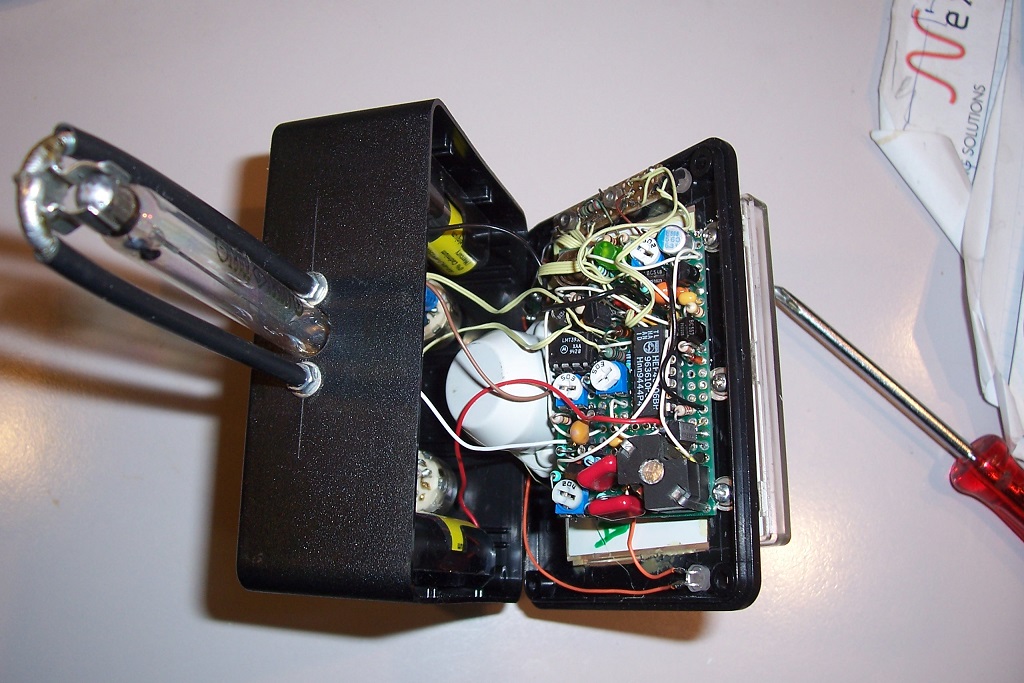
(just 1 or 2 square centimeters on the top right; the rest is the HV converter, pulse amplifier & processor, integrator, etc)
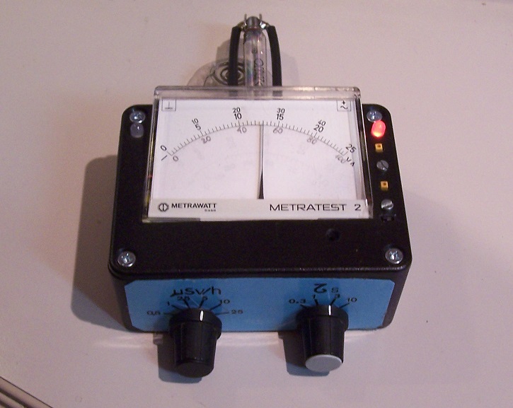
This is the finished GM detector: the current drain is ~5mA from 3 AA batteries:
(just 1 or 2 square centimeters on the top right; the rest is the HV converter, pulse amplifier & processor, integrator, etc)
This is the finished GM detector: the current drain is ~5mA from 3 AA batteries:
Attachments


This PSU handles a number of functions for battery-operated devices:
It is basically a LDO regulator, but it also performs the ON/OFF function with a single push-button, the power indication, lo-bat indication and short-circuit protection.
It is absolutely minimalistic, comprising only 2 discrete transistors.
This pic shows the core of the circuit subjected to simultaneous input and load ripple:
Impressively simple. C2 (100nF), first schematic, is that added to slow down the loop?
Now I may have the attention of two particularly skilled "old farts", I like to ask you a question: A member recently wanted to use a 1KVA transformer after a Variac (looking for a lab/bench power supply for amplifier testing ,posting #25) but the manufacturer stated that the transformer will not transfer much power below 75% of nominal input voltage. Does that sound correct? High level of remanence?
Zalig Kerstfeest
No, to speed up.The emitter is connected to the +rail via D1=reference voltage and the base with C2 to the minus rail.Impressively simple. C2 (100nF), first schematic, is that added to slow down the loop?
The transformer has a max current independent of the output voltage, so the VxA power will be less with less voltage.the manufacturer stated that the transformer will not transfer much power below 75% of nominal input voltage. Does that sound correct? High level of remanence?
Zalig Kerstfeest
Joyeux Noel.
Mona
Well, now you are ready when something goes wrong at Doel or TihangeThis is the finished GM detector: the current drain is ~5mA from 3 AA batteries

Mona
Impressively simple. C2 (100nF), first schematic, is that added to slow down the loop?
As Mona hinted, it does rather the opposite: it increases the loop gain of the regulator in AC.
I had to drop it in the final version: it interfered with the ON/OFF circuit
A neat shortcut indeed, but I wanted to reuse as much as possible the (linear) scales of the salvaged galvanometer, and anyway I preferred explicit controls of the sensitivity and integration time for this one> the finished GM detector
A "Geiger Counter"?
Here's a clever (no range switch) compact job from long ago.
To elaborate, 75% of the nominal voltage means 75% of the power for an ideal transformer, except of course the transformer has a finite regulation, and the I*R drop will remain the same irrespective of the operating voltage.The transformer has a max current independent of the output voltage, so the VxA power will be less with less voltage.
At low voltages, the proportion of the losses will become increasingly dominant
Or anywhere else in Europe, thus proving that some aspects of the Union actually work....Well, now you are ready when something goes wrong at Doel or Tihange
- Status
- This old topic is closed. If you want to reopen this topic, contact a moderator using the "Report Post" button.
- Home
- Amplifiers
- Power Supplies
- A PSU controller on a shoestring