I’m upgrading a Harman Kardon 930 receiver’s phono stage with Muffsy that should sound much better. The Muffsy required +/- 15 V DC power which the HK930 doesn’t provide so, as advised by Muffsy’s designer Skrodahl, I also installed a modified Muffsy power Supply connecting it to HK930’s +41 V DC and ground.
The problem is that Muffsy’s ground and turntable input connectors may not be connected to HK930 ground so I got a strong hum and other bad things. The thread with details is here: https://www.diyaudio.com/forums/analogue-source/324635-bipolar-dc-supply-phonostage-hk930.html
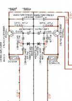
I see two ways of solving this problem and don’t know if any of them will work. First, make a circuit that lowers +/- 41 V of the HK930 main PS to +/- 15 V, as member friendly1uk suggested (see picture). In this case, Muffsy’s ground can be connected to HK930 ground since there is no virtual ground.
Second, use a DC to DC converter chip with input of +20 V DC from HK 930 preamp PS to get +/- 15 V; however, in this case I don’t know if I can ground Muffsy to the HK since the chip creates a virtual ground.
Which way is the best or there are some others? Thank you.
The problem is that Muffsy’s ground and turntable input connectors may not be connected to HK930 ground so I got a strong hum and other bad things. The thread with details is here: https://www.diyaudio.com/forums/analogue-source/324635-bipolar-dc-supply-phonostage-hk930.html
I see two ways of solving this problem and don’t know if any of them will work. First, make a circuit that lowers +/- 41 V of the HK930 main PS to +/- 15 V, as member friendly1uk suggested (see picture). In this case, Muffsy’s ground can be connected to HK930 ground since there is no virtual ground.
Second, use a DC to DC converter chip with input of +20 V DC from HK 930 preamp PS to get +/- 15 V; however, in this case I don’t know if I can ground Muffsy to the HK since the chip creates a virtual ground.
Which way is the best or there are some others? Thank you.
Attachments
In my view the "clean" way is to reduce the already existing +/-41V supply voltages to the proper +/-15V supply voltages and use the already existing signal ground. That should be "fool-proof" (no offense intended). You can use the symmetrical voltage dropper circuit you show but better performance with the same complexity can be achieved with a set of LM317/337.
Alternatively you can use +41V to GND , create a virtual ground for the phono amp and couple the audio signal from the phono amp to the pre-amp capacitively. This will not be simpler and the risk of various unwanted noise phenomens is higher. I would not go for this option.
Alternatively you can use +41V to GND , create a virtual ground for the phono amp and couple the audio signal from the phono amp to the pre-amp capacitively. This will not be simpler and the risk of various unwanted noise phenomens is higher. I would not go for this option.
Thank you. That KISS approach I would prefer after all the frustration with separate Muffsy PS.
Perhaps you know some LM317/337 circuit published somewhere on some kit or PCB utilizing LM317/337 that could be purchased?
Perhaps you know some LM317/337 circuit published somewhere on some kit or PCB utilizing LM317/337 that could be purchased?
In my view the "clean" way is to reduce the already existing +/-41V supply voltages to the proper +/-15V supply voltages and use the already existing signal ground. That should be "fool-proof" (no offense intended). You can use the symmetrical voltage dropper circuit you show but better performance with the same complexity can be achieved with a set of LM317/337.
Alternatively you can use +41V to GND , create a virtual ground for the phono amp and couple the audio signal from the phono amp to the pre-amp capacitively. This will not be simpler and the risk of various unwanted noise phenomens is higher. I would not go for this option.
Just to give you an idea. You may find the same on E-bay. A US manufacture?
Aiyima LM317 / LM337 +/ 1.5V 37V Adjustable Dual Voltage Regulator Power Supply Module-in Voltage Regulators/Stabilizers from Home Improvement on Aliexpress.com | Alibaba Group
LM317 LM337 DC Adjustable Regulated Power Supply Module Board Positive and negative can adjustable-in Amplifier from Consumer Electronics on Aliexpress.com | Alibaba Group
DIY LM317+LM337 Negative Dual Power Adjustable Kit Power Supply Module Board Electronic Component-in Integrated Circuits from Electronic Components & Supplies on Aliexpress.com | Alibaba Group
Found that top limit of the LM317 regulator input voltage is 40V. Since I have +/- 41V out of the HK power supply, need to use LM317HV/LM337HV with the top limit of each 60V.
You are right that the input capacitors supplied have voltage ratings of 25V and 35V. That is not sufficient for 41V.
But, it is not true in the sense that LM317 and LM337 can handle up to 37V measured from input to output. You have 41V on the inputs and 15V on the outputs. That is 26V. If you used the regulators for +/-2V you would have a problem.
You need a version with 50V (or 63V) rated input capacitors.
Thank you for suggestions.
The #1 outputs only +/-5V and said it could be changed with selecting resistor values. I'd pass it.
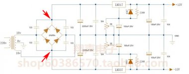
The #2 and 3 provide adjustable output voltage which is good. Number 2 requires AC but since it has schematics (the only one which does) I can tinker with it and supply +and - 41 V DC to points shown by red arrows, removing diodes. Also, I will change LM317 and LM 337 to corresponding HV versions available at Mouser.com and check if any electrolytes should be increased in voltage as well. EDIT: didn't see your previous post. Yes they should.
The #3 of your suggestions looks good BUT it doesn't have the schematics. I can guess but it's better not to.
Another idea is stay with LM317/337 rather then with the HV versions and have +/- 41V dropped to +/- 37 or so volt with dropping resistors.
The #1 outputs only +/-5V and said it could be changed with selecting resistor values. I'd pass it.
The #2 and 3 provide adjustable output voltage which is good. Number 2 requires AC but since it has schematics (the only one which does) I can tinker with it and supply +and - 41 V DC to points shown by red arrows, removing diodes. Also, I will change LM317 and LM 337 to corresponding HV versions available at Mouser.com and check if any electrolytes should be increased in voltage as well. EDIT: didn't see your previous post. Yes they should.
The #3 of your suggestions looks good BUT it doesn't have the schematics. I can guess but it's better not to.
Another idea is stay with LM317/337 rather then with the HV versions and have +/- 41V dropped to +/- 37 or so volt with dropping resistors.
Just to give you an idea. You may find the same on E-bay. A US manufacture?
Aiyima LM317 / LM337 +/ 1.5V 37V Adjustable Dual Voltage Regulator Power Supply Module-in Voltage Regulators/Stabilizers from Home Improvement on Aliexpress.com | Alibaba Group
LM317 LM337 DC Adjustable Regulated Power Supply Module Board Positive and negative can adjustable-in Amplifier from Consumer Electronics on Aliexpress.com | Alibaba Group
DIY LM317+LM337 Negative Dual Power Adjustable Kit Power Supply Module Board Electronic Component-in Integrated Circuits from Electronic Components & Supplies on Aliexpress.com | Alibaba Group
Attachments
Last edited:
The #2 could be a suitable starting point for a bit of modification. LM317/LM337 specs say 37V maximum operational and 40V maximum non-operational. You will have 26V operational and non-operational. Only if you short-circuit the outputs, you may have up to 41V. But, that board has an input rectifier that leaves a 1.2V drop. Thus, the 41V becomes 39.8V. You are below the "absolute maximum ratings" even for a shorted output. A shorted output is unlikely for a fixed, build-in load.
My impression is you can use this board, bought as a "DIY kit", if you change the 2200uF/35V capacitors to 2200uF/50V capacitors.
You can change for Mouser components as you like but, if I am right, your HK930 is made in Japan with parts that resemble very much what I see on the photos. I took another HK apart recently.
Last edited:
It just come to my mind that the Muffsy power supply that is used to power the phono stage is a LM317/LM337 type! Then, why buy a new one-just mod this.
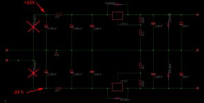
Looked at its schematics and saw that I can feed +V and -V in it the same way we discussed. The only problem is that capacitors are 2000uF/35 V which requires either replacing them to 50V to as you suggested OR use dropping resistors to lower + and - 41V. Since I have resistors on hand but doesn't have new capacitors, I'll go this route.
Please look at the schematics. The dropped +/- 33V will be applied as shown by red arrows. I don't have crossed out input diodes. The Muffsy power supply ground will be connected to HK 930 chassis ground and turntable input jacks will also be grounded same way.
Attachments
Generally I am not a fan of dropping resistors because the voltage is heavily dependent on the current consumption. I prefer drop-diodes but 41V to 33V with diodes is (too) many diodes. Let's hope the current consumption is rather stable.
The way the circuit is shown, the first 2200uF will have 41V across them unless you place dropping resistors to replace the diodes. 4R7 cannot be dropping resistors because the value is far too low. They must serve as RC filters. I will propose you to put a 10uF across each 3K3 resistor in order to improve noise performance. With the resistors shown, the output voltage will be just below +/-14V.
The dropping resistors are to be included.
Used two pairs of 48 Ohm/0.5 W resistors in series for dropping, mounting them on a separate enclosure. According to the "dropping resistor calculator", 41 V should be dropped to 31.4V IF the current consumption is 0.1A. Other connections were made as planned in posting #9.
It turns out there is +/- 42.7 V as B+/B- now after complete recap; +/- 41v was before. The voltage after dropping resistors at Muffsy PS entry was +/-40.0 V DC; I was afraid that capacitors rated at 35V will explode but they survived at least for a short time. The output voltage was +/-15.0 V so the PS was working.
The dropping resistor calculator shows with 42.7 V input a 96 Ohm resistor produces 40 V output if the consumption current is 28 mA. However, this might be just idling current different from one Muffsy consumes if a phono stage actually amplifies signal. If Muffsy consumes more, voltage at the input should be less dangerous for 35V caps. On the other hand, I don't use phono stage all of the time and then it's 40V at the input.
Will do some measurements of input PS voltage under load and try to find dropping resistors of larger value. Changing caps is a safe alternative but I don't want to do Mouser order just for 4 parts.
Last edited:
Working!
Used 330 Ohm 1/2 Watt as dropping resistors and the voltage went down from +/- 42.7 V to +/- 34.6 V. Muffsy PS outputs +/- 15V DC as it should. Also grounded the RCA input jacks of the phono inputs.
Result: no hum, no violent woofer movement, playing some record now and everything sounds great. It's perhaps a bit more hiss that I would like it to be but otherwise sounds fine.
Thank you FauxFrench for guidance and many in-depth advices.
Working!
Used 330 Ohm 1/2 Watt as dropping resistors and the voltage went down from +/- 42.7 V to +/- 34.6 V. Muffsy PS outputs +/- 15V DC as it should. Also grounded the RCA input jacks of the phono inputs.
Result: no hum, no violent woofer movement, playing some record now and everything sounds great. It's perhaps a bit more hiss that I would like it to be but otherwise sounds fine.
Thank you FauxFrench for guidance and many in-depth advices.
Happy to hear it is working. The hiss is most likely the phono-amp and not the power supply. That's life.
- Status
- This old topic is closed. If you want to reopen this topic, contact a moderator using the "Report Post" button.
- Home
- Amplifiers
- Power Supplies
- Guidance needed in choosing a bipolar power supply for a phono stage