I saw quite often on ebay, aliexpress different parts pcb and so on in order to build a psu and i wish to build my own. Should power a hybrid amp which requires a 26v/0.8 and as well a topping d50 dac 5v/2. I never did anything like this therefore i really need you're help. The only sure thing is that the solder is already in HOT 
Regards,
Regards,
Last edited:
You should find this interesting, depending on your expertise level of course.
Basic Linear Power Supply Circuits Design
Basic Linear Power Supply Circuits Design
You should find this interesting, depending on your expertise level of course.
Basic Linear Power Supply Circuits Design
interesting, thanks
G'day,
A small comment on supply voltages and power levels for a start: If the "hybrid amp" is a power amplifier, 26V/0.8Amp sounds little likely. 0.8A is too little for a power amplifier.
The TP50 uses a 5V/3A power supply.
Do you want to assemble your own power supply kit?
Do you want to design and build your own power supply using power regulator ICs?
Do you want to design and build your own power supply from discrete components?
I'm also new to this and considering building some psus.
I have this board in my watched items. Looks quite nice if you need DC.
HiFi Single Power Supply Rectifier Filter Board Kit For 1969 Amplifier PSU | eBay
And also similarly
DIY KITS HIFI Stereo Power Supply Board 63V 2200Uf X 8+MUR860G X 4 6008728722130 | eBay
I guess feed these from a toroid or laminate transformer and apart from voltage regulation you are nearly there?
An AC psu is something for me to learn as at the moment I power my Dacmagic straight from a 12v toroid. It works but I know it isnt correct!
I'm also new to this and considering building some psus.
I have this board in my watched items. Looks quite nice if you need DC.
HiFi Single Power Supply Rectifier Filter Board Kit For 1969 Amplifier PSU | eBay
And also similarly
DIY KITS HIFI Stereo Power Supply Board 63V 2200Uf X 8+MUR860G X 4 6008728722130 | eBay
I guess feed these from a toroid or laminate transformer and apart from voltage regulation you are nearly there?
An AC psu is something for me to learn as at the moment I power my Dacmagic straight from a 12v toroid. It works but I know it isnt correct!
These are nice rectifier and power decoupling boards.
A traditional power supply includes four elements:
1) A transformer for converting the net voltage to a suitable AC voltage.
2) A rectifier arrangement (often a bridge rectifier).
3) Power line decoupling capacitors (temporary energy storage).
4) A voltage regulator, often linear.
1)+2)+3) form an unregulated power supply with little power loss but some ripple and voltage variations with net voltage variations and loading. Useful for most power amplifiers and generally uncritical applications.
If 4) is added to 1)+2)+3) if forms a regulated power supply. Less ripple, constant output voltage and faster response to load changes. Unfortunately considerable power loss (heat). Useful for critical power amplifiers, pre-amplifiers, DACs etc.
You can very well start with one of the boards you suggest and then add 4) if needed. It is important to identify your needs for a a start because that affects the design of 1) and 3) in particular. If a linear regulator is used, it must have an input voltage margin such that it never saturates and regulation is lost.
4) can be designed from scratch with discrete components but generally it is recommended to use specialized ICs eventually with buffer transistors or improved regulation. Specialized ICs perform well for most use.
Linear regulators have the advantage of being adaptable by yourself through use of standard components.
The alternative to linear power supply systems is SMPS. SMPS can often be bought at good prices but are difficult to adapt yourself due to the specialized high-frequency transformer. You may add a linear post regulator after the SMPS. A post regulator can improve ripple and eventually also load response but then the attractive efficiency of the SMPS is partly lost.
Last edited:
G'day,
A small comment on supply voltages and power levels for a start: If the "hybrid amp" is a power amplifier, 26V/0.8Amp sounds little likely. 0.8A is too little for a power amplifier.
The TP50 uses a 5V/3A power supply.
Do you want to assemble your own power supply kit?
Do you want to design and build your own power supply using power regulator ICs?
Do you want to design and build your own power supply from discrete components?
G'day mate,
here is a picture of the wall wart so you can see by you're self, the hybrid amp is a class A headphone amplifier which i wish to mod as well but for this i have a separate topic open in tube amplifiers. Hopefully the information in the picture will be useful. I think assemble one is a faster and easier way, i don't have the knowledge to design a psu i'm good enough with soldering i have passion and patience and happy to put things togheter.
Attachments
A class A headphone amplifier, fine. 26V/0.8A I would make from a 30V/1.5A power adapter (SMPS), with 2200uF/50V at the output, followed by a linear post-regulator to reduce ripple and noise.
For the TP50 I would do the same but use a 9V/3A adapter instead.
ok sounds got, now i gotcha... let's make a list
Last edited:
A class A headphone amplifier, fine. 26V/0.8A I would make from a 30V/1.5A power adapter (SMPS), with 2200uF/50V at the output, followed by a linear post-regulator to reduce ripple and noise.
For the TP50 I would do the same but use a 9V/3A adapter instead.
will be nice if i could pack all togheter in one box which is going to be Psu box and from there cables that will feed dac and amp
will be nice if i could pack all togheter in one box which is going to be Psu box and from there cables that will feed dac and amp
Logically seen, keeping the linear regulators near the consumers (the class A headphone amp and the TP50) ensures better regulation for the power inputs. The two linear regulators may be arranged in one box. Then, the SMPS power adapters at a certain distance because they may radiate noise.
That is how I would do it.
It works but I know it isnt correct!
I checked my DACMagic (Cambridge Audio) and I also feed it 12Vac to keep it happy. It is absolutely correct. The reason for the AC supply is probably that it is used to generate symmetrical supply voltages through single rectification. Then charge pumps are avoided.
Logically seen, keeping the linear regulators near the consumers (the class A headphone amp and the TP50) ensures better regulation for the power inputs. The two linear regulators may be arranged in one box. Then, the SMPS power adapters at a certain distance because they may radiate noise.
That is how I would do it.
i like you're idea, can you give me a hand in selecting all the parts that i need to accomplish the mission ?
Regards,
i like you're idea, can you give me a hand in selecting all the parts that i need to accomplish the mission ?
Regards,
I will, just give me some 6 hours to remove our old kitchen (my wife's orders!) and two hours more to draw the circuits.
I'll be back.
I checked my DACMagic (Cambridge Audio) and I also feed it 12Vac to keep it happy. It is absolutely correct. The reason for the AC supply is probably that it is used to generate symmetrical supply voltages through single rectification. Then charge pumps are avoided.
Thanks for the reply.
I guess my comment was more directed at the fact that I just solely have the12v toroid and no other components.....no regulation or whatever. It is a 200VA job so shouldn't struggle to fees the DAC!
One question regarding the OPs situation....if we are to implement linear regulation to a DC supply....I can't find any ready made boards that can do 4 , 5, 6 Amps etc as may be required from a power amplifier.
Are there some out there I haven't yet landed on?
Last edited:
i like you're idea, can you give me a hand in selecting all the parts that i need to accomplish the mission ?
Regards,
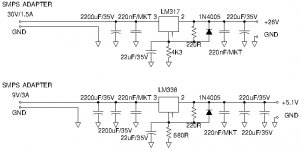
My suggestion for a 26V/0.8A linear regulator and a 5V/3A linear regulator. I chose 2200uF/35V, 220uF/35V and 22uF/35V from the needs for the 26V regulator. That voltage rating is excessive for the 5V regulator where 16V would be sufficient. However, sometimes you do not buy capacitors by the piece but in lots of 10 and then it is more practical to use few different types.
With such post regulators the ripple and step response will improve compared to your present SMPS adapters. I chose for commonly available LM317 and LM338 because they perform well and are easy to get. You can find ultra low noise regulators that will need to be put in parallel to provide sufficient current. My unqualified impression, for which I will soon be battered, is that you will not notice the difference for the actual use.
Attachments
Last edited:
Thanks for the reply.
I guess my comment was more directed at the fact that I just solely have the12v toroid and no other components.....no regulation or whatever. It is a 200VA job so shouldn't struggle to fees the DAC!
One question regarding the OPs situation....if we are to implement linear regulation to a DC supply....I can't find any ready made boards that can do 4 , 5, 6 Amps etc as may be required from a power amplifier.
Are there some out there I haven't yet landed on?
You are right, 200VA should be more than sufficient. I use only the standard 18VA. Inside, Cambridge Audio probably does as shown on the schematic - turn the 12Vac into +/- 18Vdc, symmetrical supply voltages that are then regulated down to +/- 15V. I like that design much better than having a 5Vdc input and use charge-pumps (or a micro SMPS) to bring it to +/- 5-10V. To perform the best, many high quality OP-AMPS need +/- 12-15V.
I agree with you, linear regulator kits/boards for 3-8Amp are difficult to find. Most power amplifiers run from unregulated supply voltages.
A 3-8A linear regulator is rather simple so design with an LM317 or LM337 and a 15A buffer transistor controlled by the regulator. I have made one doing +/-16V-42V, 6A and work on a +/-2-15V/3A for low power experimental use. Using a suitable IC regulator chip makes design of a linear regulator rather simple. Only if you really know your circuits, discrete power supply constructions are worth considering.
My suggestion for a 26V/0.8A linear regulator and a 5V/3A linear regulator. I chose 2200uF/35V, 220uF/35V and 22uF/35V from the needs for the 26V regulator. That voltage rating is excessive for the 5V regulator where 16V would be sufficient. However, sometimes you do not buy capacitors by the piece but in lots of 10 and then it is more practical to use few different types.
With such post regulators the ripple and step response will improve compared to your present SMPS adapters. I chose for commonly available LM317 and LM338 because they perform well and are easy to get. You can find ultra low noise regulators that will need to be put in parallel to provide sufficient current. My unqualified impression, for which I will soon be battered, is that you will not notice the difference for the actual use.
thank you very much you did an excellent job, will be so nice if i could print a pcb and then solder the stuff on it....ooo dreamin'.....
- Status
- This old topic is closed. If you want to reopen this topic, contact a moderator using the "Report Post" button.
- Home
- Amplifiers
- Power Supplies
- How to build Linear PSU?