Hi there,
I have already discussed the possibility of using a small oscillator as a supply source:
https://www.diyaudio.com/forums/pow...colpitts-oscillators-low-tech-converters.html
Here is an alternative topology, possibly original.
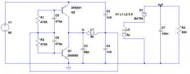
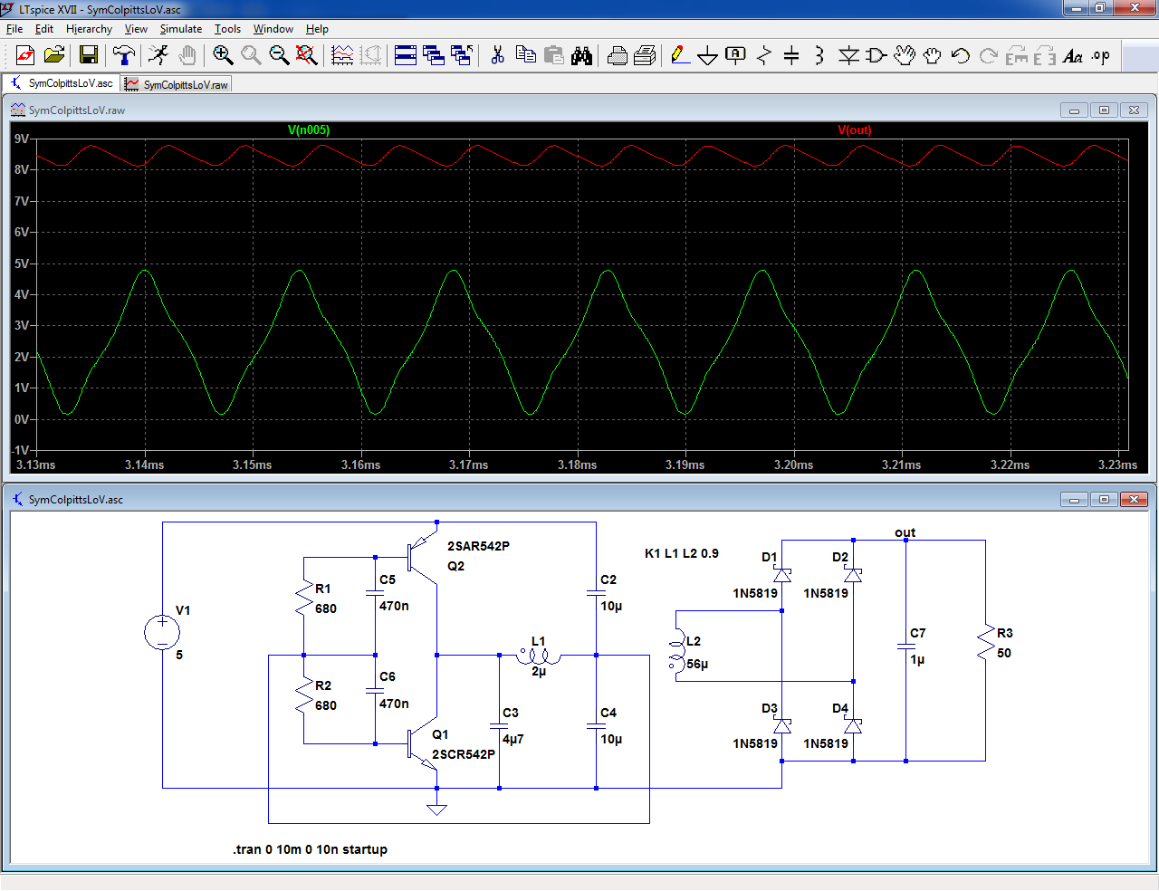
It is based on a symetrical complementary pair:
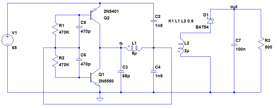
From a theoretical perspective the symmetry changes nothing, except it requires an additional active device: in AC, the transistors sex is non-relevant, meaning they are simply paralleled.
The reality is a bit more subtle though: the SE version requires an impedance, R1 in this example, to isolate the feedback node from a direct connection to the supply (this would shunt it to the GND):
Ideally, this impedance would need to be an inductance, to present a zero resistance to the supply DC current and a high impedance to the feedback signal, but in order to avoid a second inductive component, a resistance is used instead.
It is a tradeoff: it needs to be small to minimize DC losses, and large to reduce the AC losses.
In real life, the resistance is made such that DC and AC losses are approximately equal.
With the symetrical version, the need for this impedance disappears, meaning an improvement in efficiency of a few points.
Of course, trading an inductor for a transistor is not particularly advantageous, but there are other benefits:
The symmetry also means a cancellation of most even-order harmonics, resulting in a better purity (and less RFI), and energy is pumped twice/cycle into the tank circuit instead of once, making the circuit better suited to higher power levels.
Initially, I had designed the circuit to feed a small LED voltmeter module that I wanted to add as an afterthought to an already built PSU.
This PSU used a small capacitive supply for the control section, and I didn't want to add a 50Hz transformer: instead, I simply inserted the new supply in series with the existing one.
It is possible, because a capacitive supply closely approximates a current source.
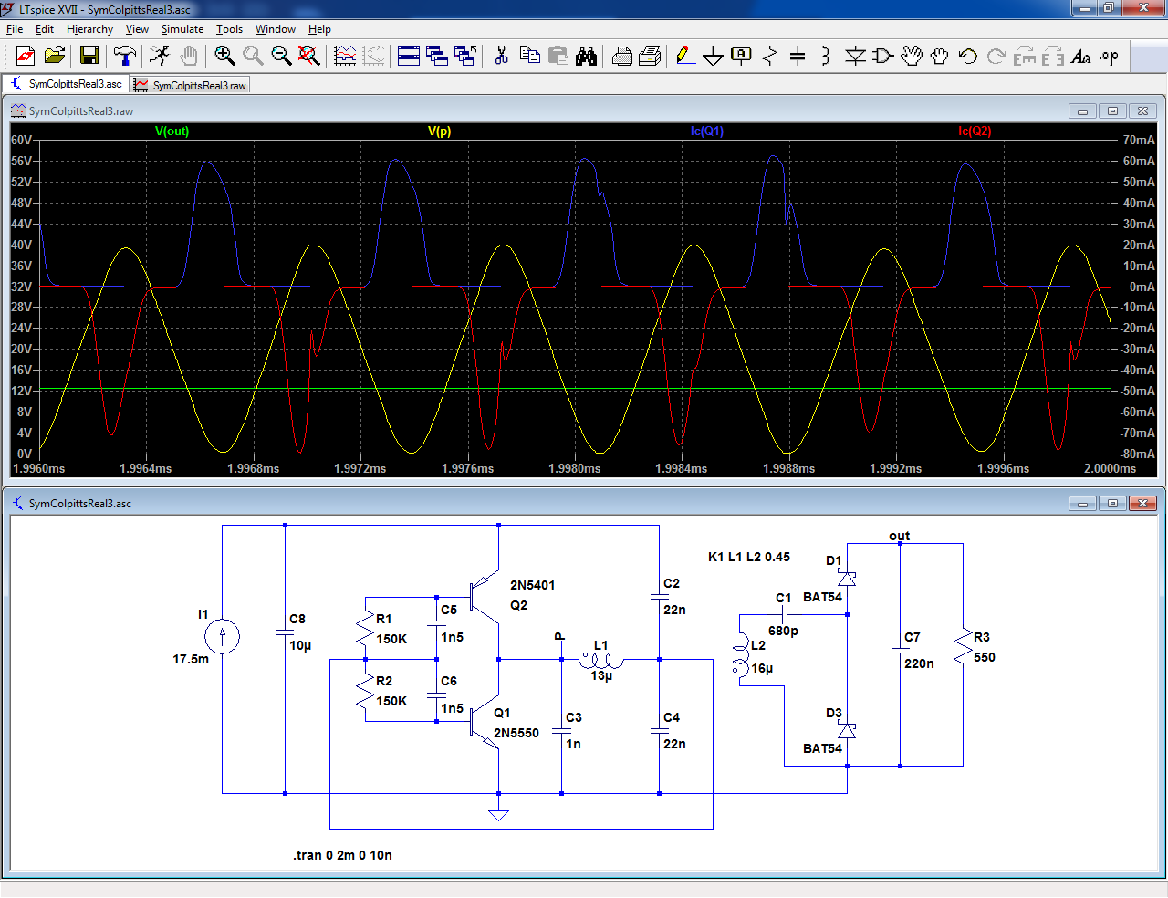
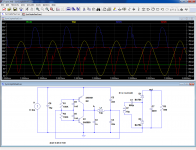
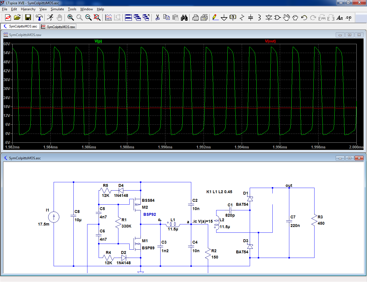
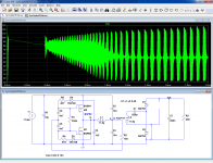
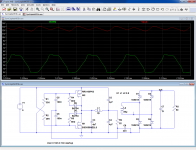
As the waveforms show, the circuit operates practically in class E:
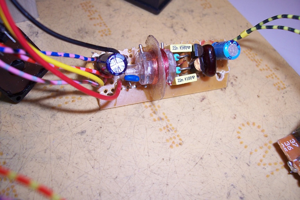
The "transformer" consists of 2 x 30 turns wound on a 10mm polycarbonate cylinder and separated by a thick mica washer:
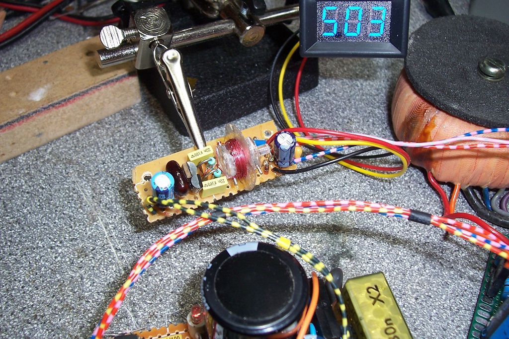
The coupling coefficient of the face-to-face coils is pretty horrendous, ~0.45, but it works with this topology, and with this geometry, the primary to secondary common-mode capacitance of the supply (the whole circuit, not just the transformer) is a record ~3pF.
Combined with the low harmonic level, it means minimal common-mode perturbations, without any need for an additional Y capacitor.
The primary winding uses a thicker wire (0.2mm) than the secondary (0.1mm), because of the resonance current.
Without a core, the Q is bound to remain low anyway, because of the stray fields permeating the windings and generating eddy currents: any attempt to increase the Q further by increasing the wire gauge results in additional eddy currents.
The solution would be Litz wire: it would reduce the eddy currents and combat the skin effect, but it is overkill for such a simplistic circuit.
This means that without tweaking, the efficiency does not exceed ~50%, which is perfectly OK for the intended applications
I have already discussed the possibility of using a small oscillator as a supply source:
https://www.diyaudio.com/forums/pow...colpitts-oscillators-low-tech-converters.html
Here is an alternative topology, possibly original.
It is based on a symetrical complementary pair:
From a theoretical perspective the symmetry changes nothing, except it requires an additional active device: in AC, the transistors sex is non-relevant, meaning they are simply paralleled.
The reality is a bit more subtle though: the SE version requires an impedance, R1 in this example, to isolate the feedback node from a direct connection to the supply (this would shunt it to the GND):
Ideally, this impedance would need to be an inductance, to present a zero resistance to the supply DC current and a high impedance to the feedback signal, but in order to avoid a second inductive component, a resistance is used instead.
It is a tradeoff: it needs to be small to minimize DC losses, and large to reduce the AC losses.
In real life, the resistance is made such that DC and AC losses are approximately equal.
With the symetrical version, the need for this impedance disappears, meaning an improvement in efficiency of a few points.
Of course, trading an inductor for a transistor is not particularly advantageous, but there are other benefits:
The symmetry also means a cancellation of most even-order harmonics, resulting in a better purity (and less RFI), and energy is pumped twice/cycle into the tank circuit instead of once, making the circuit better suited to higher power levels.
Initially, I had designed the circuit to feed a small LED voltmeter module that I wanted to add as an afterthought to an already built PSU.
This PSU used a small capacitive supply for the control section, and I didn't want to add a 50Hz transformer: instead, I simply inserted the new supply in series with the existing one.
It is possible, because a capacitive supply closely approximates a current source.
As the waveforms show, the circuit operates practically in class E:
The "transformer" consists of 2 x 30 turns wound on a 10mm polycarbonate cylinder and separated by a thick mica washer:
The coupling coefficient of the face-to-face coils is pretty horrendous, ~0.45, but it works with this topology, and with this geometry, the primary to secondary common-mode capacitance of the supply (the whole circuit, not just the transformer) is a record ~3pF.
Combined with the low harmonic level, it means minimal common-mode perturbations, without any need for an additional Y capacitor.
The primary winding uses a thicker wire (0.2mm) than the secondary (0.1mm), because of the resonance current.
Without a core, the Q is bound to remain low anyway, because of the stray fields permeating the windings and generating eddy currents: any attempt to increase the Q further by increasing the wire gauge results in additional eddy currents.
The solution would be Litz wire: it would reduce the eddy currents and combat the skin effect, but it is overkill for such a simplistic circuit.
This means that without tweaking, the efficiency does not exceed ~50%, which is perfectly OK for the intended applications
Attachments


Regarding the resistors, it is indeed a possibility, and I considered it but rejected it in the end, at least for the BJT version.How about simplifing a bit ?
For the MOS version I had to use it (with some adaptations) because of the different bias requirements.
-more on that later-
I used the current version for BJT's because the DC feedback from the collectors helps correcting the duty cycle and the DC centering of the "p" waveform in case of imperfect matching between the N and P transistors (imperfections which are unavoidable with real-world devices)
BTW, C2 and C4 could also be merged into a single cap, but I kept the two caps because real-world supplies have imperfections like noise, ripple or finite impedance and a bridge of capacitors is better at rejecting them.
C3 is a different story: its value is significantly lower, and the supply would need to be really dismal to require a similar splitting.
If the supply source is good, C2 and C4 can be merged without problem
Last edited:
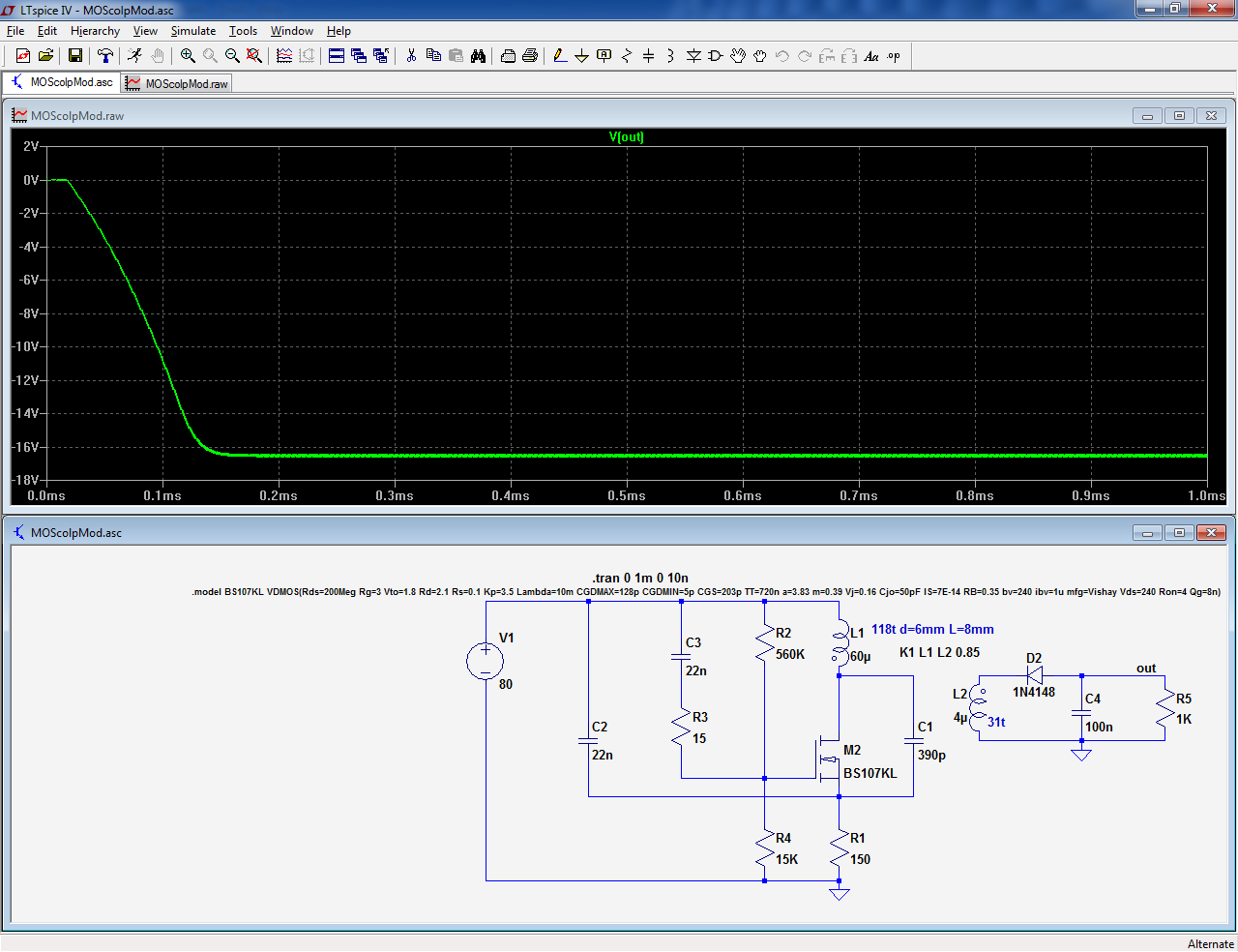
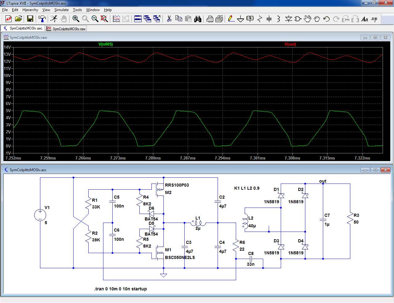
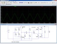
Here is the MOS version: it is based on a BSP89/BSP92 pair, but as I didn't find a quick and easy model for the BSP92, I used a BSS84 in the sim.
This means that the sim doesn't stick very well with the reality, but at least it shows how it works.
The most obvious implementation is this one, but it is rather sensitive to the threshold voltages of the MOSFETs:
If the P/N thresholds are mismatched, it is necessary to adjust R4 and R5 accordingly.
For the BSP's, the matching is good.
A more robust implementation is this one: the diodes now track the saturation voltages of the MOSFETs, allowing some degree of dispersion.
This variant works very well in reality, but very poorly in sim... go figure
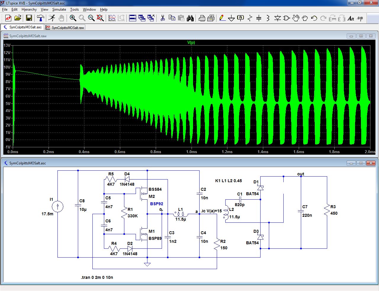
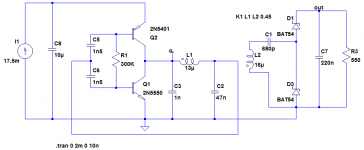
These circuits are well suited to relatively high supply voltages, but for low-voltage operation, it is preferable to split R1 into two resistors returned directly to the supply rails.
R2 is optional, its role is to optimize the feedback phase-shift for class E operation.
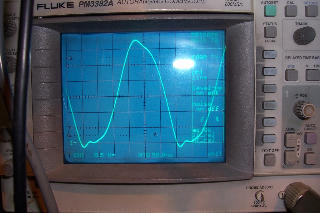
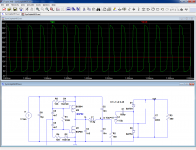
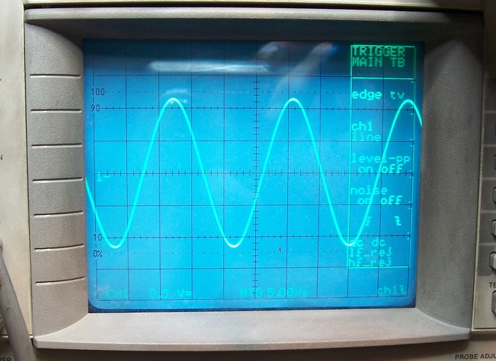
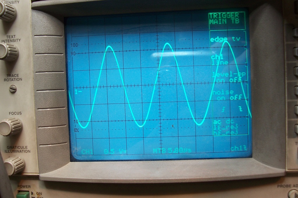
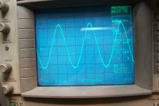
Note that the real-world waveforms are much cleaner than in sim:
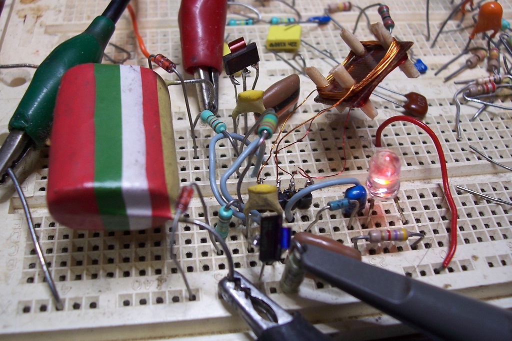
Here is the test circuit, showing an alternative implementation of the "transformer":
This means that the sim doesn't stick very well with the reality, but at least it shows how it works.
The most obvious implementation is this one, but it is rather sensitive to the threshold voltages of the MOSFETs:
If the P/N thresholds are mismatched, it is necessary to adjust R4 and R5 accordingly.
For the BSP's, the matching is good.
A more robust implementation is this one: the diodes now track the saturation voltages of the MOSFETs, allowing some degree of dispersion.
This variant works very well in reality, but very poorly in sim... go figure
These circuits are well suited to relatively high supply voltages, but for low-voltage operation, it is preferable to split R1 into two resistors returned directly to the supply rails.
R2 is optional, its role is to optimize the feedback phase-shift for class E operation.
Note that the real-world waveforms are much cleaner than in sim:
Here is the test circuit, showing an alternative implementation of the "transformer":
Attachments


Initially, I had designed the circuit with a specific field of application in mind: high-frequency (1~10MHz), current driven, low-power supplies based on air-core inductors, but it then occurred to me that the topology was also suited to other applications: it ticks all the right boxes as a base for clean and quiet isolated supplies.
To qualify as quiet, a supply needs to fulfill a number of criteria:
If these oscillators are made to operate at a relatively low frequency, 100kHz or less, and a low voltage 5~24V, they easily meet all of the above, thanks to their sinusoidal operation.
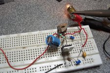
I made a crude test with two implementations: one based on BJT's and the other on MOSFETs.
For this occasion the transformer is now a 56µH choke with a few turns added on top to form the primary.
The tuning capacitors are ordinary X7R MLCCs and the transistors are BD438/439.
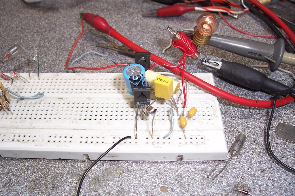
The result is surprisingly good, considering the simplicity of the setup, and its construction on a breadboard: the contact resistances have a huge effect, and if you touch any component you see the amplitude vary.
The circuit even tolerates E-caps for the larger value capacitors.
Here is the MOS variant:
The physical test circuit is somewhat different, because the best PMOS of my stock is a MTP23P06, not a very good match for the IRFZ44 I used on the other side. As a result, I had to alter the bias resistors values, but even so, a significant asymmetry remains.
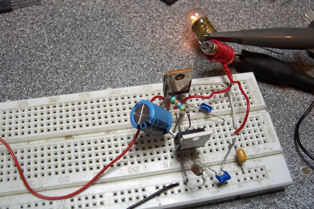
It still manages to work though.
Of course, in a real implementation, the transformer doesn't need to be that crude: it could be a properly gapped ferrite core or a metal powder toroid.
To qualify as quiet, a supply needs to fulfill a number of criteria:
-No fast-changing waveforms, even on purely internal nodes: without drastic shielding measures, fast transitions always end up spilling somewhere.
-No injection of the operating frequency into the input or output ports; this is probably the easiest point to meet, as passive LC circuits can provide any arbitrary degree of rejection.
-Isolated grounds, because ground returns should exclusively follow their respective signals, and duplicating this connection via the PSU is bound to cause problems like ground loops.
-Good common-mode isolation between the circuits: going into the trouble of having the grounds isolated doesn't make much sense if this isolation is ruined by a large common-mode capacitance, be it inherent or added like a Y cap.
If these oscillators are made to operate at a relatively low frequency, 100kHz or less, and a low voltage 5~24V, they easily meet all of the above, thanks to their sinusoidal operation.
I made a crude test with two implementations: one based on BJT's and the other on MOSFETs.
For this occasion the transformer is now a 56µH choke with a few turns added on top to form the primary.
The tuning capacitors are ordinary X7R MLCCs and the transistors are BD438/439.
The result is surprisingly good, considering the simplicity of the setup, and its construction on a breadboard: the contact resistances have a huge effect, and if you touch any component you see the amplitude vary.
The circuit even tolerates E-caps for the larger value capacitors.
Here is the MOS variant:
The physical test circuit is somewhat different, because the best PMOS of my stock is a MTP23P06, not a very good match for the IRFZ44 I used on the other side. As a result, I had to alter the bias resistors values, but even so, a significant asymmetry remains.
It still manages to work though.
Of course, in a real implementation, the transformer doesn't need to be that crude: it could be a properly gapped ferrite core or a metal powder toroid.
Attachments


- Status
- This old topic is closed. If you want to reopen this topic, contact a moderator using the "Report Post" button.