Dear all
I am currently building an amplifier with a GU-46 tube as single ended setup (thread already opened in Tube Forum).
But I now have a specific power supply question that could most probably solved in this Forum - this is why I post it here.
The GU-46 tube needs to be heated with 8.3V DC at approx. 15A and ideally zero ripple.
All voltage regulators available on the tube market and as schematics found by Google have their max at around 6.5A at 6.3V DC which is by far not enough to feed this heater.
I do not want to use an LED switching supply. And if possible also not a 3 leged regulator, since they are said to influence the sound. The heater is also the cathode of the tube and needs to be grounded.
The power transformer available is a 5-0-5 V transformer with sufficient A to feed a large DC supply. The currently used bridge rectifier is 40V 60A and should also be sufficient, delivering a raw DC of 13V (measured without load)
Does anyone have a working proposal / schematic for a very low ripple, high current 8.3 V voltage regulator?
Your help ist very appriciated
Thomas
I have a number of possibilities in store, including NMOS-based LDO's, but normally this one should suffice: it is designed as a protected, 12V/10A regulator, but the output voltage can easily be altered by modifying R4, R5, or both, using a pot for example, and the current is mainly determined by the transistors: you could use a 40A/250W one instead of the 2N3055.
The protection eats up ~0.7V, it can be removed by deleting Q4, D1, R9, R8.
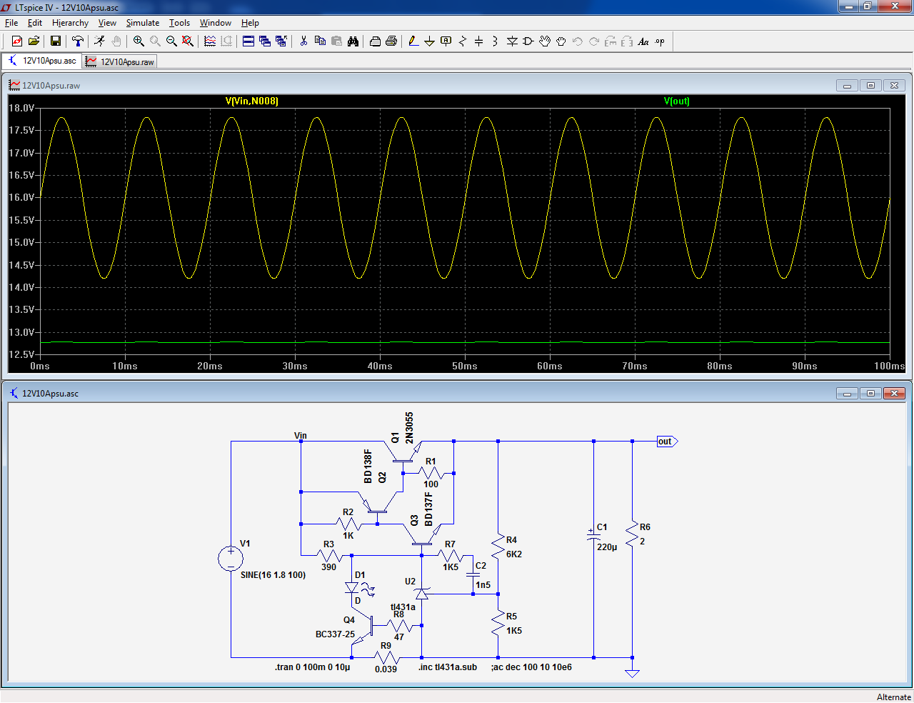
Here is the modified 8.3V version:

That said, you should measure the rectified+filtered output of your transformer at 15A: you could well need a LDO to be able to regulate
The protection eats up ~0.7V, it can be removed by deleting Q4, D1, R9, R8.
Here is the modified 8.3V version:
That said, you should measure the rectified+filtered output of your transformer at 15A: you could well need a LDO to be able to regulate
Attachments
An other thing, you will need a very big capacitor after the bridge.
Suppose 10V min before the reg (leaving 1,7V for the pass transistor) and the drop from the transformer internal resistance + that from the diodes leaves 12V peak, then the drop on the capacitor may be no more then 2V in 1/100sec at 15A.
Gives 225mF (225000µF) minimum !
Mona
Suppose 10V min before the reg (leaving 1,7V for the pass transistor) and the drop from the transformer internal resistance + that from the diodes leaves 12V peak, then the drop on the capacitor may be no more then 2V in 1/100sec at 15A.
Gives 225mF (225000µF) minimum !
Mona
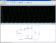
Here is a sim showing the outlook of the raw DC output from the rectifier + filter cap.
It is based on a good 300VA toroidal transformer (the minimal VA rating to reasonably do the job).
R1 and L1 aggregate the transformer's parasitic parameters as seen from the secondary.
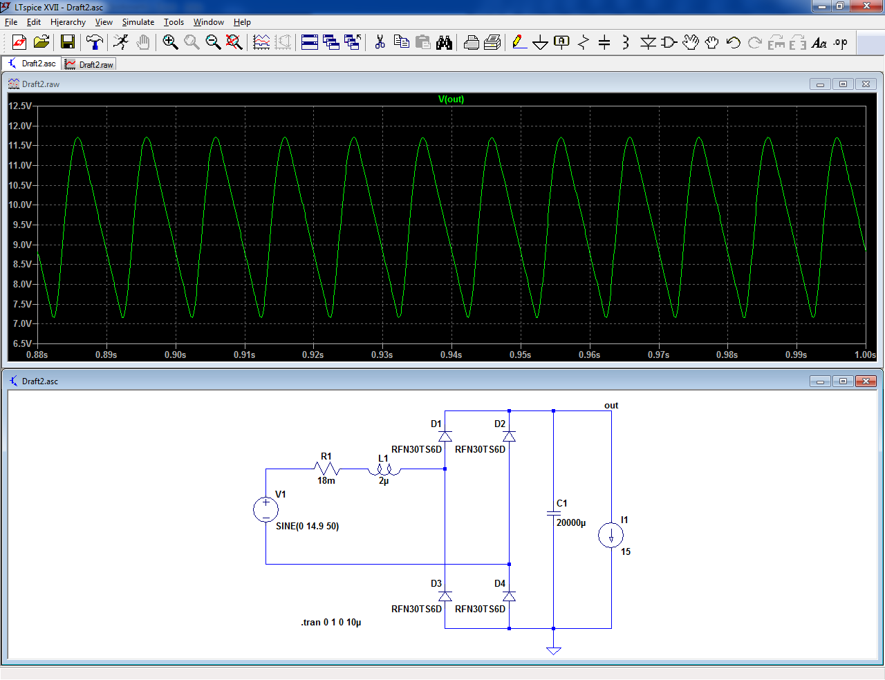
You can see that the troughs are 1V below the intended regulation target.
Note that this sim is for a nominal line voltage, and doesn't take into account any frivolities you might want to insert into the circuit, like an inrush limiter or a CMC.
If you increase the filter cap to 100,000µF, things look a bit better: now the troughs sit at ~9.7V, leaving a 1.4V margin for regulation, which is not that much: the circuit I proposed is incapable of regulating in these conditions, and various minor imperfections have not been accounted for: for example, the 100,000µ cap is perfect in the sim, but a real cap will have a finite ESR.
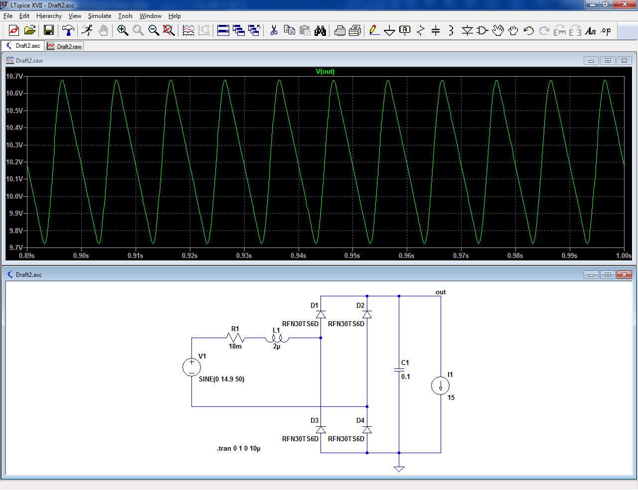
To be safer, you would need a 220,000µ cap, as Ketje suggested:
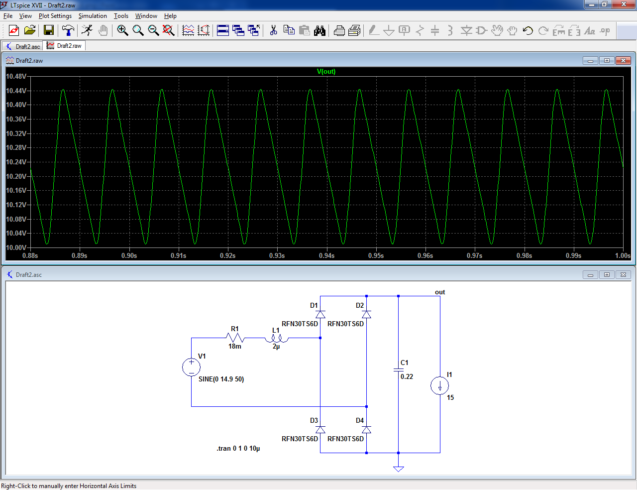
Now, you remain above 10V, but don't be mistaken, this is not ample: if the mains falls by 10%, it will become 9V, meaning you need a good LDO regulator to be half-safe.
With schottky rectifiers, you could improve the situation, but unfortunately schottky's do not like high peak currents.
Increasing the cap to more than 220,000µF is not an option because the rms current is already 27A. With 470,000µF, you would exceed the 30A limit
It is based on a good 300VA toroidal transformer (the minimal VA rating to reasonably do the job).
R1 and L1 aggregate the transformer's parasitic parameters as seen from the secondary.
You can see that the troughs are 1V below the intended regulation target.
Note that this sim is for a nominal line voltage, and doesn't take into account any frivolities you might want to insert into the circuit, like an inrush limiter or a CMC.
If you increase the filter cap to 100,000µF, things look a bit better: now the troughs sit at ~9.7V, leaving a 1.4V margin for regulation, which is not that much: the circuit I proposed is incapable of regulating in these conditions, and various minor imperfections have not been accounted for: for example, the 100,000µ cap is perfect in the sim, but a real cap will have a finite ESR.
To be safer, you would need a 220,000µ cap, as Ketje suggested:
Now, you remain above 10V, but don't be mistaken, this is not ample: if the mains falls by 10%, it will become 9V, meaning you need a good LDO regulator to be half-safe.
With schottky rectifiers, you could improve the situation, but unfortunately schottky's do not like high peak currents.
Increasing the cap to more than 220,000µF is not an option because the rms current is already 27A. With 470,000µF, you would exceed the 30A limit
Attachments
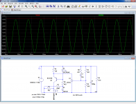
Here is a LDO adapted for 8.3V (untested in this configuration, of course).
It manages to regulate down to 100mV dropout @15A.
Combined with 220,000µF filtering and a bridge made of 100A schottky diodes, it should give you a sufficiently comfortable margin
It manages to regulate down to 100mV dropout @15A.
Combined with 220,000µF filtering and a bridge made of 100A schottky diodes, it should give you a sufficiently comfortable margin
Attachments
Ten of those in parallel ?Which 220000uF cap can withstand these high currents? Any proposals?
https://www.conrad.de/de/jianghai-e...-16-v-20-o-x-h-30-mm-x-30-mm-1-st-446200.html
Mona
I cannot mention a brand that can supply a single 220000uF capacitor for such currents. I will suggest you to use a plurality of capacitors (10000-22000uF) in parallel and arrange them such that the distance to input and output is around the same in order that they best share the current.
NB: Use a slow charge start-up circuit or your fuse(s) will blow trying to charge 220000uF.
NB: Use a slow charge start-up circuit or your fuse(s) will blow trying to charge 220000uF.
Last edited:
Big E-caps are not exceptional and do not require cutting edge technology: this one dates back from 1981 and is 97,000µF/25V.
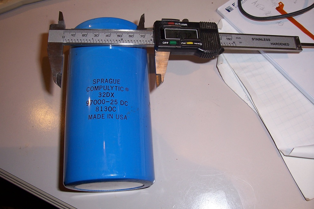
I have larger ones somewhere in my stash, but I could locate this one easily and its energy storage is the ~same as the 220,000µF/16V you need, so nothing outlandish or unobtainable.
I do not know their ripple current rating, but it's most likely sufficient.
Of course, if you need to make your construction portable, you are in trouble: this one weights a kilo or thereabout.....
The inrush current isn't a particular problem either: the energy is the same as for a 390µF used in many directly mains rectified supplies.
Attachments

The size of 1/2 liter of Kronenbourg. Impressive what can be found around in Belgie.
Actually: B41458B4220M000 EPCOS / TDK | Mouser Europe
I did not see the weight but you have to wait some 18 weeks. Price not dramatic at 50 Eur.
Actually: B41458B4220M000 EPCOS / TDK | Mouser Europe
I did not see the weight but you have to wait some 18 weeks. Price not dramatic at 50 Eur.
Here is a LDO adapted for 8.3V (untested in this configuration, of course).
It manages to regulate down to 100mV dropout @15A.
Combined with 220,000µF filtering and a bridge made of 100A schottky diodes, it should give you a sufficiently comfortable margin
Hi,
Is R7-D3 a bootstrap ?
R7 to allow Q1 to turn on at power up, then
D3 to allow D1 to conduct ?
I wouldn't call it a bootstrap, rather a startup circuitHi,
Is R7-D3 a bootstrap ?
then the regulator wakes up, making D3 to conduct and to override the (weak) startup path R7.R7 to allow Q1 to turn on at power up, then
The purpose is to provide regulation to auxiliary, internal voltages to eliminate higher order stability effects.
The main reference also benefits from this scheme, of course
Thanks for your support LV
Some more - last - questions.
When building the proposed regulator, the R5 in the schematic ist the heater itself (8.3V/15A = 0.55R), correct?
Concerning the 220'000uF cap, I found a Sprague 300'000uF /16V cap, which should to the job, large as a beercan. Weight is no issue in this build, the completed stereo Tube amp will be approximately 150kg, 1kg for a cap will be no bit deal.
This will be placed after or instead the 1000uF cap in the schematic, correct?
Where would you place the current inrush limiter (SL32-2R025) to limit the start up current when changing the caps? It has a final R of 0.06 or so Ohm when running at 15A, so probably negligable.
Is it placed after the regulator, in front of the cap or before the regulator?
Thanks a lot once again for your geat help.
Greetings
Thomas
A switching power supply like this one Affichage reglable du conducteur LCD d'alimentation d'energie de commutation de 0-24V 20A 480W 110 / 220V pour - 36,33€ will be cheaper and more efficient 
Best regards,
Marc
Best regards,
Marc
I prefer to not use switching or LED supplies
I am just now designing a 845 PP-amplifier and plan to use (or at least test) those cheap
switching power supplies.
What is the reason you avoid them ?
YesWhen building the proposed regulator, the R5 in the schematic ist the heater itself (8.3V/15A = 0.55R), correct?
No, it has to be placed in front of the regulator, instead of V1 if you prefer.Concerning the 220'000uF cap, I found a Sprague 300'000uF /16V cap, which should to the job, large as a beercan. Weight is no issue in this build, the completed stereo Tube amp will be approximately 150kg, 1kg for a cap will be no bit deal.
This will be placed after or instead the 1000uF cap in the schematic, correct?
V1 symbolizes the transformer/rectifier/filter cap combo.
It has to be placed upstream of the capacitor, of course.Where would you place the current inrush limiter (SL32-2R025) to limit the start up current when changing the caps? It has a final R of 0.06 or so Ohm when running at 15A, so probably negligable.
Is it placed after the regulator, in front of the cap or before the regulator?
This leaves two options: in the secondary or in the primary of the transformer.
I think that you have the secondary in mind, but that is going to be problematic: 19mΩ is far from negligible: with 300,000µF, the peaks of the charging current reach 60A, translating into a loss of 1.14V in the peak voltage, not something you can afford given your tight voltage budget.
Besides, a big transformer is also going to be the source of a large inrush current, and by locating the NTC at the primary, you kill two birds with one stone, without too much of a voltage penalty at the output
BTW, there might be another inrush issue: the cold resistance of the filament is certainly much lower than its running value, and this could pose problems to the regulator, if the current is too high.
As a consequence, a long delay, relay-based starter placed at the primary might be necessary.
As a consequence, a long delay, relay-based starter placed at the primary might be necessary.
- Status
- This old topic is closed. If you want to reopen this topic, contact a moderator using the "Report Post" button.
- Home
- Amplifiers
- Power Supplies
- Low voltage regulator for high current consumer