That is something I can perfectly understand: even ideally clean switching supplies (supposing such a thing exists) will have a Y capacitor connected to the output, and I would certainly not like to have such a cap in the cathode circuit of an amplifier.I am just now designing a 845 PP-amplifier and plan to use (or at least test) those cheap
switching power supplies.
What is the reason you avoid them ?
For an indirectly heated tube, I would be much less picky: after all, P-series tubes had their heather galvanically connected to the mains
...8.3V DC at approx. 15A and ideally zero ripple ....transformer available is a 5-0-5 V transformer with sufficient A to feed a large DC supply. ...
"Zero ripple" can't happen.
Are there any real data on the "sufficient" transformer? Particularly total winding resistance?? I have a gut fear you won't make 9VDC even before regulation.
Load is something over 8.3V at 15A (hot), so say 0.66 Ohms.
*Assuming* a 20Amp AC transformer with _5%_ sag we have 0.025 Ohms winding impedance.
Turn to Schade, still the best tool for such problems. (FWIW, Duncan PSUD seems to go astray with these low values.)
http://diyaudioprojects.com/Technical/Tube-Power-Supplies/figure05full.jpg
In Schade, "Em" is *peak* voltage, and the conversion from 2-diode to Bridge should be obvious. 0.025r/0.66r is Rs/R like 0.04. Read the right side of the curves (the left side is high ripple). Granting the assumed assumptions we can get 0.85 of Em, or 0.85*14.14V, or 11.9V. The Bridge will drop at least 2V (is that actual data available?) so 9.9V. The wRC to get peak voltage is about 20. 20/(6.28*50*0.66) is 0.1Farad or 100,000uFd minimum for average DC voltage.
Wire resistance WILL matter a LOT at these low impedances.
Ripple? Another Schade:
http://diyaudioprojects.com/Technical/Tube-Power-Supplies/figure07full.jpg
Rs/R like 0.04 falls in the middle of the Full Wave curves. Read up from wRC = 20, ripple factor is 0.03. 0.03*9.9V is 0.3V. This is in RMS, peak-peak is like 3X higher, 1V. This suggests ripple dips must fall to 9.4V, which leaves very little margin for a 8.3V regulator.
Wall-voltage may vary +/-5% or more. Now we could be at 8.9V on wash-day. (What my gut feared.)
E-caps are cheap. A 220,000uFd has been proposed and (look it up) can support the ripple current. Paralleling will increase ripple rating. Going to wRC = 100 (five 100,000uFd) will cut first cap ripple to 0.2V peak-peak, lifting the ripple dips a part-Volt. I am undecided about 0.2V buzz on a HIGH voltage heater. You would think the signal would overwhelm the heater buzz, al-most. But a resistor and another cap-pack would get the 9V down nearer 8.3V, get 100Hz down and the higher harmonics way down. 0.047 Ohms with another five 100,000uFd (cheaper in 10-pack) is 7Hz, so 0.07 reduction at 100Hz, 14mV peak-peak ripple.
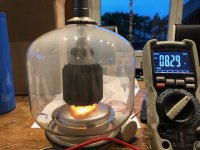
Just wanted to inform that the proposed regulator in Post #5 from Elvee works very well.
It is made up as follows
- bridge rectifier 60A/40V
- SL32-2R005
- Common mode choke 1.3mH/20A
- 300000uF Sprague Powerlytic 36DX
- Elvees's regulator
delivering 8.3V DC with not measurable AC
Unfortunately my GU-46 tube seems to have lost vacuum, it develops smoke inside when heater, something I have never seen in any other tube. Tube will be replaced.
Thanks
To all of you
Attachments
Last edited:
Before increasing anything, I would need to know the purpose of such a manipulation: just increasing the impedance without changing anything else will cause a concomitant fall in the output voltage, if the open-circuit voltage is not corrected.
Do you want to implement some kind of soft-start, or current-drive?
Do you want to implement some kind of soft-start, or current-drive?
No, high output impedances are said to have a positive influence on clearness of the sound on directly heated tubes.
Some high quality DC heater regulators have high output impedances therefore.
But I can't say if this is the case with these large transmitter tubes too.
The regulator Elvee developed works very very well concerning regulation and remaining AC, as I found out in my test circuit. There ist no need to change this therefore.
I will be able to judge its sound Impact later
Thanks once again
In fact, you would more or less like a current drive, rather than a voltage one, but that's a completely different type of regulator, and I am afraid I have nothing of the kind in store, unlike the LDO.
I will think about it, see if there is some kind of magical shortcut, but I am not too optimistic: these CCS-like circuits need some headroom to be able to operate, and it seems that you currently have none, or thereabout.
It would be interesting to know the present operating margin (input-output differential when operating at the rated load), preferably instantaneous (measured with an oscilloscope).
If the "clearness" of the sound is the motive, perhaps that changing the mode of operation to a gyrator within the audio band could do the trick?
I have attempted to tamper with the LDO, to degrade its output impedance.
The task isn't easy, because the circuit had been designed for exactly the opposite: it is a good and stiff voltage regulator, and every aspect of its topology has been designed with that objective in mind.
This means that it resists stubbornly all watering-down attempts.
In the frequency domain, it is possible to obtain some results, but the mods upset completely the transient operation.
Here is the best I could obtain: for the audio band, the output impedance becomes ~50mΩ.
This may not sound much, until you realize that the initial value was around 6µΩ: in fact, that is an "improvement" (sort of) of 10,000x or 80dB.
To go higher would require an entirely different circuit, with a current-sensing resistor somewhere, which would be problematic given your low voltage margin.
Anyway, the actual effect of such a gimmick is bound to be extremely marginal: it would slightly increase the cathode resistance and alter the repartition of the current over the filament length, and there are probably more important factors to worry about, like the injection of common perturbation through the heater, and the way the actual signal is coupled into the heather/cathode
Attachments
Still I'd be interested in arguments against feeding these GU46 heaters off a 8.3V CT winding. Looking at the 8.3V, ~15A data, these cathodes appear to be real briquets with a huge thermal capacity, so hum issues shouldn't be expected even in a SE application.
Best regards!
Best regards!
- Status
- This old topic is closed. If you want to reopen this topic, contact a moderator using the "Report Post" button.
- Home
- Amplifiers
- Power Supplies
- Low voltage regulator for high current consumer