Hello all the genius people. I want to built a power supply which gets 130 volts DC as an input and gives me 120 volt DC as an output. I have found a circuit but i do not understand how it works it is actually for a input higher than 204 volt DC and it give a constant 200 volt DC in output. I thought i could use the same circuit. If anyone of you can help me understand the circuit and tell me which parameters i must change to get the desired circuit. i have attached the diagram of the circuit. Please help me i want to build the circuit for my project.
Thanks
Thanks
Attachments
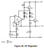
The key information is right on your diagram.
Vout = (R2/R1) * Vref
If you change the ratio R2/R1, you change the output voltage. Evidently there is some internal reference voltage, and the LM10 can be wired to multiply this up to any other voltage.
The LM10 datasheet is readily found, and has more detail. I strongly urge you to read it. I've snipped a key drawing below. There was also an LM10 applications note, jam-packed with (boastful) details.
Attachments
Texas Instruments has an off-the shelf HV regulator TL783 which is a $1.98 part for 120V out. You could also use a Microchip LR8N3 and an external pass transistor. The latter is actually stable.
I have a tube of LM10 -- useful back decades ago as it has its own Vref. I used it in a logarithmic converter.
I have a tube of LM10 -- useful back decades ago as it has its own Vref. I used it in a logarithmic converter.
LM10 is an OP-AMP that can operate from very low supply voltages (down to 1.2V). If you look at the schematic, the supply pins for the LM10 (pins 4 and 7) are connected across D1+D2+basis-emitter of Q2. That leaves around 2V of supply voltage. Thus, D1+D2 serve to set the supply voltage for the LM10.
D3 and D4 serve to bring the voltage regulation potential inside the output range of the LM10. The LM10 has to control the base of Q1 which has a potential above the supply of the LM10.
Honestly, I don't like this type of floating reference regulator. Is it important for you to make a 130V->120V regulator or is your goal to make the design you show work?
Last edited:
Other way to look at it.
On R1 is allways 0,2V so the current is 0,2/2k=0,1mA.Same current flows in R2 and the node R1-R2 is at the output voltage level.
Well, adjust R2 for 0,1mA at the output voltage.For 130V you need 1M3.
Mona
Mona, well analyzed and explained. Les Belges sont forts!

Osmanelectro, how much current do you need?
At least change D1+D2 into a single 3V9 zener and D3+D4 into a single 2V7 zener. This minimum supply voltage concept reduces performance.
Last edited:
i did try to change the relation between R1 and R2...
To what?
Leave the 2k alone. Reduce the 2Meg in proportion to what you want. Mono gave you one value. I'd just drop 2meg to 1Meg and see if voltage came to half.
Hello, thanks for the reply. Yes i must have 120 volts in the output. I am using this power supply to charge a series of capacitors. Which further discharges through a coil in form of coil gun. SO the output voltage should not cross the 120 volt limit. The current is not a big issue here because i am just using it to charge the capacitors. I thought a 1 amp limited power supply would be fine. I worked with the circuit a bit today. I have choosen R2 to be 1M3 and R1 to be 2k to get the 120 volts but now the thing is that i must have some load of like 0,03 amps before it keep the voltage constant in the output. It means there has to be a power loss of 3,5 to 4 watt.
I understand your explnation about the 2 diodes d1 and d2 regarding providing supply to opamp but i am still not completely sure about the role of other 2 diodes. I know they are here to do the voltage regulation but i can not see it how it works together with Q1. Thanks for the reply ")
Does anyone of you know how can i simulate the above circuit in Pspice. I cant find the LM10 in opamp library but if you guys know how i can import the model of LM10 or if anyone knows how else i can simulaye the circuit.
Thanks
Use the functional diagram from 7.2 in the LM10 datasheet with generic parts. Or if you have a day or so, use the schematic on the first page of the datasheet to write up your own spice list.
Hello, do you have any idea of how i can find the transfer function for the given circuit. I am doing it for the purpose of stability to find the stability of the regulator. i want to make a control system for the given circuit and then analyse the stability with help of bodeplot etc..
Hello, do you have any idea of how i can find the transfer function for the given circuit. I am doing it for the purpose of stability to find the stability of the regulator. i want to make a control system for the given circuit and then analyse the stability with help of bodeplot etc..
Figure 37 in the datasheet.
Analog Devices has an lm10 model on their site
Last edited:
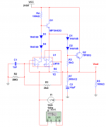
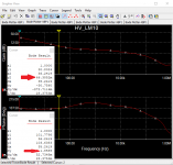
Had to think a bit more clearly about where to break the control loop. The operational amplifier in the LM10 is very slow (under 100kHz). It looks stable, but the impedance will probably be quite high.
The other issue will be the high multiplication of any noise in the voltage ref.
The other issue will be the high multiplication of any noise in the voltage ref.
Attachments
Hello
Thanks for simulating the circuit. Can i ask what program you have used to simulate this and get the bode plot? And my next question is if i want to find the transfer function with help of bode100 can i use the same method as you have done in your cirvuit? Like just putting a small resistor between the output and feedback and then measure across that resistor to get the bodeplot?
Thanks for simulating the circuit. Can i ask what program you have used to simulate this and get the bode plot? And my next question is if i want to find the transfer function with help of bode100 can i use the same method as you have done in your cirvuit? Like just putting a small resistor between the output and feedback and then measure across that resistor to get the bodeplot?
- Status
- This old topic is closed. If you want to reopen this topic, contact a moderator using the "Report Post" button.
- Home
- Amplifiers
- Power Supplies
- high voltage regulator