Hi and thank you for taking the time to read my post,
I have searched and yet to find anything relating to this subwoofer
I have a Monitor Audio RXW-12 powered subwoofer, now the amp just appeared to be dead with no signs of life at all and i love a DIY challenge, I've looked around inside and couldn't get any worth while voltage readings ect from the power supply, so I'm hoping it's just the power supply failure however after my recent experience trying to recap the power supply in my Behringer DDX3216 went badly (so that's going to be a future project hopefully as all the ADC and DAC boards are fine if i can find something to take the 8 I2s input data buses and the 4 out using 16 inputs & 8 outputs, USB or Adat ?)
anyway I've given up on switch mode power supplies and wishing to just replace it with a good old transformer as i already have some from my past project's and salvaged from other gear that's been past repair,
Dose anyone have the service manual please ?
the digital amp board has dual rail power input feeding 2 regulator's L7912CV/L7812CV so that gives the 12V dual rail for the opamps ect
there's another single power supply by the look's of it however i cant see the code on the regulator right next to it because of a cap in the way but chances are it's the 5V supply however will check before applying any power
now there's the dual rail for the main power amp and apart from the main filter cap's being rated at 50v and i haven't had the heat sink off yet to see what class D amp chip's ect it uses so that need's further investigation to see what voltage it need's
any advice on suitable power supply rating's and voltages, specially the main amp supply ?
has anyone else attempted anything like this before ?
modified one of these sub's ?
any advice welcome.....
Service manual would be priceless if any one could help,
If all else fail's i will be looking for another suitable Class D amp board to replace it and building a DIY power supply for it
Cheer's
I found the user manual, and a picture of the inside of the unit, but nothing more.
https://www.superfi.co.uk/images/manualbrochure/SILVER-RXW12.MANUAL.PDF
You can get a rough idea of the voltage based on the power and how many ohms the driver is. A 2 ohm driver needs a 32V swing to use 512W. 4 ohm requires almost 45V based on simple ohm's law. Most of the class D amps I've used could take a range of voltages. If you had an adjustable PS you could start around 20V or so and go from there.
Last edited:
thank you very much for your advice,
yes i searched the internet and apart from user manual and pic's i've found very little,
apart from just buy another monitor audio amp (they must be making a killing selling replacement's for known defective modules due to design and inferior part's)
i think my best bet is to check exactly what Class D chip it actually uses and search for the data sheet and look a little deeper into the circuit and how it's powered and work from there because the other 2 supplies have track's leading to known voltage regulators so fairly easy to work out using there data sheet's
i have thought about using a variable power supply however i haven't got one with dual rail output, is there any simple DIY instruction's on building capable of delivering a high current as stated above i have the transformer's and have no problem building power supplies able to provide a couple of Amp's,
however 45V sound's about right given the 50V high value smoothing cap's on the input just didn't realise such a low dual rail voltage could give around 500W however i have little experience with Class D amplifiers,
i will have to check the data sheet of the class D chip because i think i have an ideal 50V dual rail transformer that would also provide the other voltages needed, would this also benefit from extra 10'000uf capacitors ?
could i just use the 12V trigger provided from the amp to switch it on by use of a relay please ?
I think 50V/50V will be too high. It will rectify to 70V/70V. Within reason, the larger reservoir capacitors, the better.
As far as the trigger, you might know better than I do, you have it in front of you")
As for adjustable split rail supply, a normal linear supply plugged into a variac comes to mind...
Also getting 500W RMS from a device that says it requires 500W from the wall means it's made of magical 100% efficiency parts which, of course, don't exist. I'd be surprised if it was more than 400W to be honest.
That said, the thought of a 500W replacement (you have the enclosure and driver) says buying one of these: IRS2092S 500W Mono Channel Digital Amplifier Class D HIFI Power Amp Board + FAN | eBay
And using your 50/50 transformer/10,000uF caps might be an easier way to go. Don't do it if the driver is 2R though...
As far as the trigger, you might know better than I do, you have it in front of you
As for adjustable split rail supply, a normal linear supply plugged into a variac comes to mind...
Also getting 500W RMS from a device that says it requires 500W from the wall means it's made of magical 100% efficiency parts which, of course, don't exist. I'd be surprised if it was more than 400W to be honest.
That said, the thought of a 500W replacement (you have the enclosure and driver) says buying one of these: IRS2092S 500W Mono Channel Digital Amplifier Class D HIFI Power Amp Board + FAN | eBay
And using your 50/50 transformer/10,000uF caps might be an easier way to go. Don't do it if the driver is 2R though...
Last edited:
the transformer i think is 50V DC after being rectified from AC however will have to check,
i also have an Onkyo TX 875 i've had for year's ready to strip for part's with a huge transformer however i think that's 65V DC dual rail and also provides all other voltages needed and then some, (on that point wonder how modular the amp section is as i haven't looked apart from seeing two rows of amp driver boards un-though don't have high hope's of being able to do much with it apart from de-solder and salvage common used parts from and dispose of the rest)
Yes i have been looking at that option of buying another class d board amplifier however i want to first try and get the built in amp working as the input stage has some dsp functions that apparently tune the driver to the sealed box it's in, however i have thought about trying the sealed box and driver with one of my PA amp's and using the behringer ultrdrive's low pass filter ect and see how it sounds without it,
thank you for your advice and guidance, its very much appreciated
I checked and all my transformer's are to high in voltage or wouldn't provide enough current however,
I've seen a Harman Kardon AVR 1500 for sale really, really cheap and close by as it's spares or repairs as it's developed issues however the power supply is fine and as i only want the transformer and will probably depopulate the boards of all usable common parts ect for future projects an trying out ideas as im getting back into the diy/repair/modification, i checked out the service manual,
Harman Kardon AVR 1500 Service Manual (Page 52 of 74)
on page 52 bottom left it shows the rectified voltage as 48v +/- split rail for the amplifiers output stage plus 2 more secondary winding's providing 15v+/- and 5v +/- respectively so that would hopefully provide me with "close enough" voltages needed with the two lower voltages having there own on board regulation anyway and with the transformer being designed to actually drive 5 channels at a quoted 100-150w each (quick google search) i'm confident it will be able to provide enough current to the class D amp to satisfy its hungry power requirements driving a single 12" 500w subwoofer however im yet to check exactly what chip the class D amp uses and find its data sheet hopefully it can work with the 48v +/- transformer, i will have the time over the weekend to look a lot deeper into the actual amplifier module to see exactly what voltage range it can actually take and update the thread with my findings
Last edited:
just to update the thread,
it appear's when removing the amp board i've unfortunately court one of the little cap's on a riser board and ripped its track up so i deem the hole board now beyond repair as i'm not skilled enough nor do i see it worth my time trying to repair it as i can't confirm its actually working or this was one of the faults,
however i've taken some pic's
(Hope this works as first time i've tryed)
here's a pic of the smps,
here's the amp board
Dropbox - Screenshot_20181104-210523.png
The subwoofer is really decent quality along with the box with proper internal braising,
hear's some pic's of the speaker..
as stated on the rear of the speaker it is in fact 4 ohms and had little hope of actually repairing the inbuilt power supply and amp board but was worth looking into,
now's the question of, do i go with a class D replacement like the subwoofer came with or use a class A/B ?
the class D amp would fit in the back on the speaker just as a replacement however a class A/B would have to be house external to the subwoofer and has cooling benefit's ect
i have several power transformers to choose from and build my own supply, as stated above i have an onkyo tx-875 with fully working amp stange so would it be possible to bridge 2 or 3 channels ?
i also have PA amp's i could also use and put in a nicer case or hide out of sight
not shore if i my pic's shared so here's a link to them,
Dropbox - Shared pic's - Simplify your life
cheer's
it appear's when removing the amp board i've unfortunately court one of the little cap's on a riser board and ripped its track up so i deem the hole board now beyond repair as i'm not skilled enough nor do i see it worth my time trying to repair it as i can't confirm its actually working or this was one of the faults,
however i've taken some pic's
(Hope this works as first time i've tryed)
here's a pic of the smps,
An externally hosted image should be here but it was not working when we last tested it.
here's the amp board
An externally hosted image should be here but it was not working when we last tested it.
An externally hosted image should be here but it was not working when we last tested it.
Dropbox - Screenshot_20181104-210523.png
The subwoofer is really decent quality along with the box with proper internal braising,
hear's some pic's of the speaker..
An externally hosted image should be here but it was not working when we last tested it.
An externally hosted image should be here but it was not working when we last tested it.
An externally hosted image should be here but it was not working when we last tested it.
as stated on the rear of the speaker it is in fact 4 ohms and had little hope of actually repairing the inbuilt power supply and amp board but was worth looking into,
now's the question of, do i go with a class D replacement like the subwoofer came with or use a class A/B ?
the class D amp would fit in the back on the speaker just as a replacement however a class A/B would have to be house external to the subwoofer and has cooling benefit's ect
i have several power transformers to choose from and build my own supply, as stated above i have an onkyo tx-875 with fully working amp stange so would it be possible to bridge 2 or 3 channels ?
i also have PA amp's i could also use and put in a nicer case or hide out of sight
not shore if i my pic's shared so here's a link to them,
Dropbox - Shared pic's - Simplify your life
cheer's
Last edited:
looking closer at the pic's i've taken of the amp board i've also spotted what look's like one of the regulators has let the magic smoke out......
take a look at the L7812CV of the pic
Dropbox - DSC_0218.JPG
so it's probably got more issues,
and so i'm currently investigating the connector between the input controller board and the amp it's self you can also see in the pic, it's got 7 pin's and i've already found a +12,-12 coming directly from the regulator's and two grounds so that's 4 out of 7 discovered, just the other 3 to work out, i'm thinking one will be a power signal to turn the amp on and audio signal,
if i manage to work out the pinout i will share it and be going with a class D replacement
Last edited:
I'm yet to do more testing however here's an update,
I have got the input stage of the rear panel to apparently work from a separate split rail regulated power supply using +/- 12v and have found the "power on" signal that only go's high (+v) when it's turned on or senses the incoming signal depending what it's set to do on the rear switch however it's only around 8.5 volts in respect to 0v ground and has a delay that could be ideal to drive a 5v (with a resistor) relay used to turn the power supply for the amp on and off as required as i'm already supplying the +/- 12v from another linear regulated power supply
i'm shore i've also found the signal and ground wires to feed the replacement amp
i've figured most of the 7 wires out apart from one
here's some pic's to help anyone in the future do such a mod/repair/replacement or possibly upgrade the internal amp and power supply as the box is solidly built and the 12 inch driver is really high quality being monitor audio however they must of turned to someone else to build the amp and power supply that has let it down big time
Dropbox - DSC_0267.JPG
Dropbox - DSC_0268.JPG
now looking at the pic's here's what i've got....
1, Black wire - power on signal- when turned on it rises to +8.5v in respect to 0v
2, Brown still looking into this....
3, Red wire -12v negative (needs regulation)
4, turquesa wire 0v power supply
5, Yellow wire +12v positive (needs regulation)
6, black wire audio signal negative/ground
7, white wire audio signal positive
this should make it an easy job for anyone with basic skill's to replace the built in amp and supply for one of their choosing as this back plate input module takes care of most of the functions like turning it on using the sensing an incoming audio signal or remote 12v signal from the AV receiver and also has the low pass filter and all EQ setting's and volume controls,
now i need to decide on what amp ??? Class D or Class A/B ??? any advice welcome...
and what power supply ?? transformer or smps ?? any advice welcome
cheer's
Last edited:
Hi kodabmx, my driver is 4 ohm's and unthough i failed trying to reuse the amp i have now managed to get the main part i wanted to use as stated above as it takes care of most functions just providing a processed audio signal and another to turn it on as required so i'm now looking a suitable amp board
you mentioned this earlier on in this thread...
I've found this one on amazon here in the UK
KKmoon IRS2092S Mono-Channel Digital Audio Amplifier Class D HIFI High Power Amp Board 500W: Amazon.co.uk: DIY & Tools
do you think it would be suitable for my need's ?
have you got any personal experience with this board please ?
you mentioned this earlier on in this thread...
buying one of these: IRS2092S 500W Mono Channel Digital Amplifier Class D HIFI Power Amp Board + FAN | eBay
And using your 50/50 transformer/10,000uF caps might be an easier way to go. Don't do it if the driver is 2R though...
I've found this one on amazon here in the UK
KKmoon IRS2092S Mono-Channel Digital Audio Amplifier Class D HIFI High Power Amp Board 500W: Amazon.co.uk: DIY & Tools
do you think it would be suitable for my need's ?
have you got any personal experience with this board please ?
Thanks for your posts and pictures.
By chance I have one of these units with the dead amplifier...
The driver and box are near mint but the amp is a dog of a thing...mine's covered in tarry goo, presumably for component damping, and so most parts are only recognised by their outline beneath...!
I've taken a different path from you....removed the electronics and sealed the box leaving only a set of conventional speaker terminals.
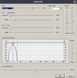
I'm not after earthquake simulations so have tested with a spare Plinius power amp to satisfactory levels and am now installing foobar2000 and it's recent sub-woofer plugin on my pc.
The plugin is wonderfully configurable !
I'll feed to a usb soundcard with2.1 capability and thence to my main amp and the plinius power amp.
Quite a fun little project and more useful than I thought the yard-sale purchase would be.....(got it for about 3 of your British Pounds...!!)
By chance I have one of these units with the dead amplifier...
The driver and box are near mint but the amp is a dog of a thing...mine's covered in tarry goo, presumably for component damping, and so most parts are only recognised by their outline beneath...!
I've taken a different path from you....removed the electronics and sealed the box leaving only a set of conventional speaker terminals.
I'm not after earthquake simulations so have tested with a spare Plinius power amp to satisfactory levels and am now installing foobar2000 and it's recent sub-woofer plugin on my pc.
The plugin is wonderfully configurable !
I'll feed to a usb soundcard with2.1 capability and thence to my main amp and the plinius power amp.
Quite a fun little project and more useful than I thought the yard-sale purchase would be.....(got it for about 3 of your British Pounds...!!)
Attachments
Last edited:
Hi Drone7
yes the sealed box and subwoofer is of quite high quality and worth reusing/modifying and it matches the rest of my atmos speaker setup being all monitor audio silver however i'm lacking the subwoofer and hence me doing this when watching movies and concerts ect
as i've now got the main part of the rear panel to function from a separate 12-0-12v regulated power supply providing the processed audio signal and the power on signal,
my current thought's are going one of two direction's
1, install a transformer and class D amp in place of the original however it's a sealed box with just a little heat sink along the rear that didn't help thing's as the heat has little way of escaping the unit and i did notice the smps power supply appear's to be powered on all the time so the failure don't surprise me abut i've already found a signal that go's high to turn the amp on and off that could of been used to turn the rest of the power supply on and off as required like i am planning on doing
2, like you however put a speakon connection they use in PA audio gear for the speaker input on the rear plate along with a XLR line level output and use the 3'rd pin for the power on signal as they share the same negative and building an external monoblock as i have PA amp's knocking about i could modify as they normally have loud fan's to keep them cool and find a fancy looking box for it with an easier way to upgrade and play with trying other amp's and setup's ect and leaving only a small regulated 12-0-12v transformer and power supply inside the subwoofer with a slim chance of going wrong
any advice moving forward with this project wound be gratefully received
edited version hasn't posted so,
Hi Drone7
yes the sealed box and subwoofer is of quite high quality and worth reusing/modifying and it matches the rest of my atmos speaker setup being all monitor audio silver however i'm lacking the subwoofer and hence me doing this when watching movies and concerts ect
as i've now got the main part of the rear panel to function from a separate 12-0-12v regulated power supply providing the processed audio signal and the power on signal,
my current thought's are going one of two direction's
1, install a transformer and class D amp in place of the original however it's a sealed box with just a little heat sink along the rear that didn't help thing's as the heat has little way of escaping the unit and i did notice the smps power supply appear's to be powered on all the time so the failure didn't surprise me but i've already found a signal that go's high to turn the amp on and off that could of been used to turn the rest of the power supply on and off as required like i am planning on doing
2, i'm thinking about just putting a speakon connection (they are used in PA audio gear for the speaker input/output) on the rear plate along with a XLR line level output and use the 3'rd pin for the power on signal as they share the same negative and building an external monoblock as i have PA amp's knocking about i could modify however they normally have loud fan's to keep them cool and get quite hot so i'd need to find a fancy looking box for it with a huge heat sink however would make for a better solution in the long term without possible heat buildup issues inside the subwoofer box an easier way to upgrade and play with trying other amp's and setup's ect and leaving only a small regulated 12-0-12v transformer and power supply inside the subwoofer with a slim chance of going wrong and a better chance of actually powering the sub properly
any advice moving forward with this project wound be gratefully received so please leave a comment....
Just a quick update,
i've ordered the small class D amp from amazon just to hear how it sounds when installed hopefully retaining a stock look and operation of the subwoofer as it will only be used to watch the odd movies or concert's
KKmoon IRS2092S Mono-Channel Digital Audio Amplifier Class D HIFI High Power Amp Board 500W: Amazon.co.uk: DIY & Tools
OK so the amp board arrived today and i have basically tried it connected to rear input panel and driver, and i'm blown away by the power that little amplifier has when powered from a proper split rail +/- 65vdc
I'm currently repairing one channel of a cloud vtx750 (a rack mount 750w RMS PA amplifier made in the UK) with an easy modular design with a huge toroidal transformer and separate power supply board with the bridge rectifier and 6 huge cap's on i used to provide the amp with the required 65Vdc +/-
I've also got the rear panel control board properly working with a separate linear regulated power supply providing +/-12vdc
i was correct with the audio signal pinout and ground however it appear's to be really loud, unfortunately i currently have no way of reading this but you can only have the main volume on the top of the unit turned up a little and the volume out the subwoofer is crazy loud however when turned right up it soon overdrives the amp's input into distortion ???
what is the best way to manage this, reduce the audio signal ?? i have had a basic look at the input board and there appears to be an opamp driving the audio out ? however it's all smd components and don't have much experience modifying the gain on them
apart from the high output to the amp issues that can be worked around anyway it worked impressively well
now i'm going to strip an old Onkyo TX-875 for it's power supply ect as it's got a huge high current transformer providing +/- 64vdc plus other part's i can now use that i've held onto from a past failed project (unfortunately the HDMI board had failed so i tried something else but the main microprocessor prevented me from using it as a multi channel DAC and amp using I2S input, got the DAC board working from a cubietruck on it's own and the main amplifier however put it all together and the processor would stop the amp outputting any sound so i eventually gave up on the project and saved it in the shed for future salvage or should i with to revisit my original idea with a fresh perspective,
would it be OK to just leave the spare secondary winding's unused and not connected to anything ?
all that's left to do is come up with a way of using the power on signal coming from the input board so it turns on two relay's, one high power relay to turn on/off the main transformer for the amp and another with some kind or delay to connect/disconnect the driver from the amplifier, is there any easy way of making a turn on delay however disconnect straight away once the power signal is removed ??? any advice please ??? possible transistors/ways of implementing a turn on delay or other means as it provides a +8.5Vdc when turned on
I think this project is coming together nicely, reusing an old power transformer i had laying around and a cheap Class D amp from amazon and i should have a lovely monitor audio subwoofer working
thank's to anyone that's given me support and encouragement along the way and anyone who contributes in the future
Last edited:
Hi, i first powered the rear input board connected to the amplifier just feeding the split rail +/- 12v input of the amplifier and no other power applied to the amplifier board while testing and as stated got it to work properly when finding what pin dose what however i was unable to discover what one of the wires actually did and upon powering up directly on it +/- 12v just not knowing what that last connection did the auto power on/off function fail's to work however i can remember a voltage being on that connection but the rest of it worked as expected so i'm thinking it must be for checking the amp as with no voltage applied it wont actually come out of standby so possibly a protection function however it still worked fine just the LED stayed red and there was on power applied to the power on output
However I've been also thinking both as a DIY audio fanatic that will want to try other amplifiers ect in the future and most importantly safety wise, did i really want to stick a huge transformer and digital amplifier that both create heat and stick them in the back of a wooden sealed box and risk the firework's in my living room when the heat's built up or something go's wrong ?
after thinking long and hard exploring all possible outcomes... not really....
So I've drilled a tight fitting hole and just installed a female neutrik Speakon connection i already had on the rear soldered it directly to the subwoofer and made shore it's all tightly sealed and put back together despite me getting the rear input board mostly working and going to build an external amplifier that i'm more comfortable with doing that has proper ventilation ect
however i hope this thread can possibly help anyone else in the future that actually want's to replace the amplifier and power supply as a DIY replacement class D amp and suitable SMPS would work however i'm not experienced enough with the SMPS's to be comfortable using them let a alone putting one in a sealed wooden box
My next project is looking into using the power amplifier from the Onkyo TX875 on it's own because it came out as a complete module with power supply, removing all the complicated digital and logic control board's I'm left with a high quality power supple with a couple of relay's controlling the power to transformer and from the secondary winding's to the main amplifier board and another voltage regulator board and the only other connection's i can find both looking around the boards the selves and the service manual is 7 line level input's/7 speaker output's and a couple of logic lines plus fan control that went to the processor to do with the protection/monitoring and controlling the cooling fans
one signal for " PROTECT " coming from a couple of transistors fed from IPRO & VPRO and as i understanding it they are over current and over voltage and VOLH sensing so i will be starting another thread hopefully to get this beast of a amplifier modual working just a 7 channel power amp
I've started a new thread and would appreciate everyone checking it out and contributing any help, support and guidance to implement my own protection circuit in order to use the beastly 7 channel amplifier module safely from the Onkyo TX-875 with another pre-amp, i've gutted all the complicated control logic and processor board's out of it and I'm just left with a huge transformer power supply and the power amplifier module with 7 duplicated amplifier channel's with just a bunch of 12v relay's to control power to and from the transformer and 7 speaker output relay's also the 7 line level audio input's so there's only my lack of understanding of how the protection circuit worked to implement & reuse the 3 IPRO, VPRO & VOLH sense line's coming from the power amplifier stage as i've hopefully worked everything else out so it's the only thing really stopping me from using it so any guidance at all would be gratefully received,
Advice/guidance on reusing the power supply & power amp module from the Onkyo TX-875
cheer's
Advice/guidance on reusing the power supply & power amp module from the Onkyo TX-875
cheer's
Last edited:
RSW 12
Hi Paulflan.
Thanks for your explanations. My RXW are blown in the switch mode supply unit. It seems that the 500 W amp. is ok. I think it is a bridged monoblock running on appr. 40 -0 - -40 V.
It was very helpful to read what You have found out, as it is not easy to get a diagram.
I am considering to use a transformer supply from my scrap yard and hope to make the filter/input section to work. Else i will follow your advice in building a separate 12 + 12 V supply and a chinese monobloc.
Best regards
Mogens A
- Home
- Amplifiers
- Power Supplies
- advice needed, Monitor Audio RXW-12 Subwoofer power supply