No response, but just to correct my mistake, for the record.
Turns out the Benchmark uses a SMPS but does conventional Class H to obtain the rails.
John Siau (the chief EE) says they considered switch mode rails but went linear.
Now I have looked more closely at it I am not surprised, it's harder than it looks.
On the other hand I learned that latest RF telecommunications amplifiers do use a similar scheme, envelope trackers with multiphase switchers @ many MHz.
So it's doable if one has the $$$.
David
LabGruppen buck converters are asynchronous type, They can Source the current but cannot Sink it, which poses a problem above 7khz, where the collector voltage envelop no longer follows the signal and raises the floating voltage which was meant to be around 7V in this case to somewhat much higher say 50vdc plus, you run into lot of issues then, the reason they have VHF prptection kicks in when you give a strong HF signal.
I finally returned to this project and had a look at more recent developments.
I noticed that the Benchmark AHB2 amplifier uses this technique and achieves the best performance I have seen measured for any amplifier.
So it looks like the idea was more than reasonable.
The time lapse was also a chance to reexamine the idea with fresh eyes.
The reduced power dissipation means I can simplify the OPS, no need to parallel several OP transistors for power, only to keep current low to reduce beta droop.
So now FET OPs look better and I can reduce the quiescent current from my earlier estimates.
I have learned more since the last thread post but would still like to have some other people's inputs.
Is there more interest in the idea these days or are people still stuck on linear supplies and/or off-the-shelf SMPS?
David
I'm using a SMPS off the shelf to give 24V. Using a medical supply may sound overkill but it has PFC, isolation, plus a buttload of filtering. Output is 24V 150mVpp.
That will then drive a non-isolated DIY boost to take from 24Vdc to 230Vdc. It's possible to do 600W but the only issue is PCB and bus bars for the higher current at that power. For now this initial version will be providing 230V 500-600mA which is enough for my needs and will sit on a 300W SMPS power supply. It also has an uncouth, un-valve like, 6mF of capacitance to drive.
Things you have to consider with SMPS are what happens under almost zero load (quiet times), at full load (max current) and the speed of transition that the system can support. A number of them utilise blanking of PWM or varying of switching rate to vary the power supplied. This can lead to the switching encroaching on the audio spectrum.
Last edited:
Did you get further with it Dave?
Thanks for the interest, I have been super busy at work for the last 2 years!
But I did do some LTSpice simulations of a planned linear amplifier in class H with a simple buck rail tracker on each power rail.
Eventually I was able to reach pretty nice numbers with distortion @ 20 kHz <0.001% @ full power and idle dissipation of only a few watts.
The usual disclaimer that this is just a sim, but I used meticulous models that have previously been verified with built hardware that matched the sims almost perfectly.
So I believe this will work and plan to build a prototype, just as soon as work eases off, whenever that is...
You have some ideas and plans or just curiosity?
Best wishes
David
Curiousity as I have nice PA amplifiers but eventually along the lines I want to stear it into a less powerdemanding and lightweight system.
Would be nice to use and endorse good ideas from this wonderfull forum.
Ive been eyeing:
your https://www.diyaudio.com/community/threads/greenamp-modulated-class-g-output.332657/page-19
Our very missed Andrew Lebon`s https://www.diyaudio.com/community/...ogy-where-are-this-diy-projects.165467/page-5
and a few others.
Cheers!
Ok, that was bit earlier, I ran a lot of simulations to explore options since then!
I eventually found that Class-H with the rails modulated by a switch mode circuit looked the best solution.
A buck switcher achieved excellent results, and is quite simple, after I sorted out issues, mainly with the comparator and switch drivers.
I tried GaN switches and found lower loses but in practice the faster transitions would probably be more troublesome for radiated noise.
Sorry to learn about Andrew, I had missed that news.
Best wishes
David
Carver never built audio tracking power supplies, that was part of the propaganda. They used the magnetid field amplifier name for a especial type of power transformer, one with enough core area, but very few turns, such that it would saturate under noload condition. by controlling the input voltage using a triac, based on rectified output voltage, the transformer was kept out of saturation. I once measured such a transformer, it would saturate at half the supply voltage under no load conditions. The transformer was based on EI lamination stacked very high; the much smaller winding area could support the few turns it was designed for yielding a compact and low weight transformer.

Your reference to this thread inspired me to look more closely at Yamaha's EEE circuit.
It's pretty close to what I proposed, a ZVS switch mode power supply to switch mode rail trackers to drive a linear class B+ amplifier.
The patentable "EEE" bit seems to be the hybrid, parallel path in the rail trackers.
That's quite clever, as expected from Yamaha, not just advertisement buzz words.
The linear amp looks almost overbuilt, I would expect a very robust product, and I believe that's the usual opinion of these amps.
Not like some of the Carvers!
Thanks for the link.
Best wishes
David
I believe the predessessors to the eee models have been measured to be very good amplifiers and the smaller models without fans, therefore very suited for home use. I haven't yet found and compared measurements between the two lines. Also I dont know if there are a lot of different versions of eee.
We sold very lightweight and affordable 200w8r mixers late 90ies. -can't imagine their power supplies etc; were as good as their more expensive offers.
It wouldn't pay for me to build one from the ground since pro gear is often sold VERY cheap second hand here in Denmark.
Cheers!
We sold very lightweight and affordable 200w8r mixers late 90ies. -can't imagine their power supplies etc; were as good as their more expensive offers.
It wouldn't pay for me to build one from the ground since pro gear is often sold VERY cheap second hand here in Denmark.
Cheers!
They were not “trackers”, but they were class H discrete stepped power supplies. Average power draw was reduced, and if it wasnt that little bitty transformer would catch on fire.Carver never built audio tracking power supplies, that was part of the propaganda. They used the magnetid field amplifier name for a especial type of power transformer, one with enough core area, but very few turns, such that it would saturate under noload condition. by controlling the input voltage using a triac, based on rectified output voltage, the transformer was kept out of saturation. I once measured such a transformer, it would saturate at half the supply voltage under no load conditions. The transformer was based on EI lamination stacked very high; the much smaller winding area could support the few turns it was designed for yielding a compact and low weight transformer.
And they were relatively SLOW rail switches. They’d stair-step properly when the signal frequency was below about 1kHz, and just latch full ON at higher frequency. That was “ok” for typical use, but pro use for anything other than subwoofers didn’t end well. Today it’s easy to build a class H stepped supply that will work at 20 KHz (QSC made millions of them).
Last edited:
I don't think the forum had a "like' option back when this thread kicked off but thank you for your contributions since the start.They were not “trackers”, but they were class H discrete stepped power supplies.
They have been very informative, do you do PA professionally or just interested?
Best wishes
David
Not really what one would call “professionally”, but off and on most of my life. Started out in the DJ wars back in the early 80’s, but realized I’d never have two nickels to rub together or equipment that was worth a damn if I remained in that life and wanted to stay clean and above board. I opted for college and a lucrative career as an MMIC designer. Get to play with amplifiers every day, just a different kind. With that kind of financing I could build equipment I could only drool over back in high school, but doing actual PA work was an occasional thing. Last gig I did was in 2015, but I’ve since started building a whole new rig, one that you can not just hear but feel the bass from space. For when I can finally say goodbye to this job and get my new “facility” built. Most of the speakers are done, but working on replacing four racks of amps with all DIY iron pigs. Back in 09, I got a prototype 4kW class H up and running on the bench, but it’s been a challenge making something manufacturable and physically road worthy. So often the project sat for years at a time. Thats what happens when you can’t give it your full attention or able to throw unlimited funds at the problem. A few grand a year is fine - but can’t add a bunch of zeros to that if I want to finish building my ranch and stay out of debt.
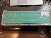
Latest gen of the amp is 4 step class H with options to run the supply on +/-155 or +/-180, depending on how the toroids are wound. 10x MJL21193/4, plus drivers and 6 commutators. No tracking, just discrete steps. Has the comprehensive protection circuitry I spent about 2 years developing (again, off and on). Just ordered a board set, going to give it a go and see if I can get this version to fit in 4U without running into more problems I can’t solve.
Latest gen of the amp is 4 step class H with options to run the supply on +/-155 or +/-180, depending on how the toroids are wound. 10x MJL21193/4, plus drivers and 6 commutators. No tracking, just discrete steps. Has the comprehensive protection circuitry I spent about 2 years developing (again, off and on). Just ordered a board set, going to give it a go and see if I can get this version to fit in 4U without running into more problems I can’t solve.
Attachments
Last edited:
That looks very impressive, and expensive!just discrete steps.
Did you consider switch mode trackers rather than 4 step class H?
The 4 steps obviously help the efficiency but are still lossy, whereas a switch is not, at least ideally.
(Obviously in reality there are transition and switch driver losses.)
4 steps also adds quite a bit of complexity.
For my proposed circuit the sims indicate it's feasible to have just one output and one switch per side, which is nice.
But that's only 600 W, for your power requirements maybe it wouldn't work out so neatly, no surprise that an amp that size has complications.
In any case, my compliments on your work.
Best wishes
David
And your toroids?
4kW is a lot, soft start issues? Mass?
I am tempted to use 3 phase even for my much smaller system
Last edited:
The problem with any switching converter is that it doesn’t scale up gracefully. It needs to be electrically small or it doesn’t behave like the simulations. Electrically and physically small can’t get any heat out, even the 5% at this power level. I didn’t want to get into an endless loop chasing timing issues across an 18 inch PCB, or slowing down rise times to 10 microseconds and dealing with just as much switching losses as I have in conduction loss of class H. H class with 3 or 4 steps is efficient enough, and switching is limited to the audio frequency. All the power is below a kHz, so that part pretty much vanishes. The hexfets run cooler than the commutating diodes. 10 output transistors in parallel can handle the dissipation - there are only 8 per bank in my CA18’s. And they are only 2 step.
The toroids are twin Antek 15632’s, with additional quad 22V winding on each. That’s sized to be able to run 1/3 power at 4 ohms per channel indefinitely. One does not need full sine wave indefinitely, because that would destroy the speakers and sound more like radio static than music. But should be able to take it for say 15 seconds at a time, or run up at half average power for a track or two. Todays switch mode amps that cost $8000 apiece can’t even do that without shutting themselves off. I want the short term limit to be the 20A breaker in the distro. Trip that and you’re playing too loud, period. By then, speakers would be charcoal. But that’s not the amps fault - that’s on the user. Limiting for speaker protection is supposed to happen AHEAD of the amplifier.
Soft start is a 6 ohm 50 watt corrugated wire wound resistor in series with the mains. Shorted by an ice cube relay when the supply voltage reaches +/-140 V (The “power good” signal). Speaker sequencing begins only after power good appears, and everything shuts off when supply drops below +/-125. There is a thermal sensor on the resistor that senses if the relay fails to short it (and stays in the circuit) and kills power if that happens. Repeated power cycling will heat it up too, resulting in auto shut off till it cools enough for power to come up and stay up. That power supply supervisor is on a separate board.
- Home
- Amplifiers
- Power Supplies
- State of the Art for Tracker/Down Converter?