I wonder if someone can guide me in right direction please
I'm trying to achieve (+/-/0) 45v rails using 2 smps
I have joined negative output of one smps to positive of other to create 0v,
However when I check voltage between 0 and +/- it only reads 0.3v DC
I have separated both smps to check and both are still delivering 45v. There is no continuity between ground and outputs on either smps.
My question is using 2 smps is it acheiveable ?
If yes what am I doing wrong ?
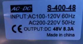
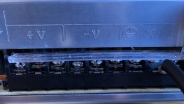
Please see attached pictures of what I'm using.
Many thanks in advance for any help
I'm trying to achieve (+/-/0) 45v rails using 2 smps
I have joined negative output of one smps to positive of other to create 0v,
However when I check voltage between 0 and +/- it only reads 0.3v DC
I have separated both smps to check and both are still delivering 45v. There is no continuity between ground and outputs on either smps.
My question is using 2 smps is it acheiveable ?
If yes what am I doing wrong ?
Please see attached pictures of what I'm using.
Many thanks in advance for any help
Attachments
If you turn the SMPS off and disconnect them from the mains do you have any measurable continuity between 0V and any of the input pins, L, N and E. I'm assuming not.
If there is no continuity of any kind then it has to be assumed the outputs are floating (which is fine), and yet when you connect the two outputs in series some interaction occurs shutting the PSU's down. The reasons why that might happen are to complex to go into here and relate to leakage at high frequency causing currents that are interpreted as a 'fault'.
You could try (at your own risk... or more correctly at the SMPS's risk because it is shown as a mains grounded product meaning it is safe for you) connecting the zero volt point of the series connected supplies to mains ground. That scenario could legitimately happen in any case with connection to ancillary equipment.
You might also find that apply a minimum load to each rail changes things.
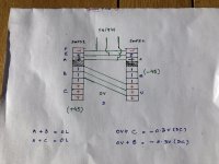
What you are doing sounds fine. Can you draw a diagram to confirm? When you say no continuity what does your multimeter show?
Sorry for late response, I was trying to draw a diagram in word but failed. So attached is a hand drawn diagram, hope it clarifies what I've done.
Many thanks for your help
Attachments
Last edited:
Without trying the above suggestion, applying 2 12V car bulbs in series did not change anything.If you turn the SMPS off and disconnect them from the mains do you have any measurable continuity between 0V and any of the input pins, L, N and E. I'm assuming not. There is no continuity
If there is no continuity of any kind then it has to be assumed the outputs are floating (which is fine), and yet when you connect the two outputs in series some interaction occurs shutting the PSU's down. The reasons why that might happen are to complex to go into here and relate to leakage at high frequency causing currents that are interpreted as a 'fault'. Most likely this is what is happening here!!
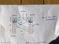
You could try (at your own risk... or more correctly at the SMPS's risk because it is shown as a mains grounded product meaning it is safe for you) connecting the zero volt point of the series connected supplies to mains ground. That scenario could legitimately happen in any case with connection to ancillary equipment. Kindly see my attached picture in next post to confirm if I have understood your instructions correctly?
You might also find that apply a minimum load to each rail changes things.
Again thank you for taking the time to help me, I appreciate it
Last edited:
The problem is perhaps the mains PE ground, since it is probably connected to the negative side. Remove the PE mains ground ad try again. There are SMPSs in which You can disconnect the ground from the case by means of a jumper.
I have checked for continuity between Earth and + or - and there is none.
There IS continuity between metal casing of SMPS and Earth only.
Thanks
Here is the picture I mentioned in above post, see the new connections in blue.
Thanks
It was that, yes. The connections look correct as well, just two series supplies.
That 0V to mains ground connection could occur anyway when you use grounded audio equipment and so it is a valid configuration.
Something else you could try although I'm not sure what it might prove...
Run both SMPS together but without the series link. Now measure the voltage differential between your two chosen series link points (the - of one PSU and the + of the other). Is there any voltage present? Any AC voltage present?
Now link the two again but this time link with a resistor instead of a direct wire. Try 10k. Do the PSU's still run? If there was voltage between the two, has that changed?
If they do run, how low can you go with the series resistor.
(The above doesn't get you a working set-up but might give some clues as to why)
Not sure where two 12v series bulbs comes into it
") as your rail voltage is 45 volts per side, 90 volts in total.
as your rail voltage is 45 volts per side, 90 volts in total.I'm interesting in a similar solution.
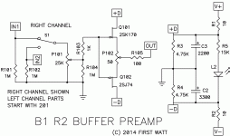
Someone in the Pass Labs forum posted a photo of their amp build with one SMPS. The power amp requires high current +v/-v and 0v. I asked if they used something similar to the power supply used in the B1 Rev2, but they did not answer. See right side of attached drawings.
Can the same power supply in the diagram be used for a high current +/- 0v power supply with a single SMPS?
Thanks,
Vince
Attachments
Someone in the Pass Labs forum posted a photo of their amp build with one SMPS.
That was done with a pair of SMPS, according to post #699 in the M2x thread.
Mooly, even if the -V near R2 is a ground, like it should have been drawn.
Your diagram just shows +V connecting to +D via a series 10 ohm and the same for -V to -D
That's drawn correctly.
- Status
- This old topic is closed. If you want to reopen this topic, contact a moderator using the "Report Post" button.
- Home
- Amplifiers
- Power Supplies
- Smps 0/-/+ rails