Rectifying 213 v AC to get 300V DC for an el84 monoblock. Making a filter circuit. Assuming it will be an RC filter I am making I got a 450v 1mf or 1000microfarad capacitor. Thing looks dangerous, like it would fry a wire if it were charged at that voltage. Transformer is a custom job. If I am aiming for 300v DC is 213V the best voltage for the trafo? What is a simple circuit I can make with the 1milifarad cap to filter the rectified power? Should I follow it with a smaller cap or is that one cap sufficient? Please point me to a safe filter circuit using such a large capacitor. Probably 150ma is the most this monoblock with 2 el84s and a 12ax7 will demand on the higher voltage line.
The transformer would be best polar or should I get it + and minus 106.5 volts and and 0v? the only filter design I could think of using plus, minus, and neutral would require two caps? Should I get the trafo made polar or +,-,and neutral? Is 213V correct for the trafo voltage?
I am only asking bscause I have never worked with such a powerful capacitor and want to be safe.
I just saw an rc filter design that uses a 500 microfarad cap as a reservoir and a 1000 microfarad cap as the smoothing cap. I like the look of that filter. I can get 2 500mircofarad 450V caps to put into the filter. Can someone please point me to a dssign for the best filter design using the 1milifarad and a half milifarad cap?
I can add a choke. Or a resistor. What givss the best current fodr a valve amp? I have read that adding an inductor can improve filtering.
Thanks
Yes. I am using those soviet clones which only take 6.3V Wondering if I should use regulators on the hv and low v sections. I can get the trafo made to any spec. for the 6.3V part I can get it slightly higher and use a regulator, or use an Rc, or Lc, or Combo filter and a fullwave rectifier
What would be the best trafo specs? Any significant advantage to using a regulator and going a little high in the voltage? I am thnking polar, only 2 taps will be easiest and unregulated. I don't know what to do and what specs to get the trafo wound to
This one will take 6.3v for the 12ax7 equivalent and 6.3v for both the el84 equivalents, and 50 ma @ 12V AC for the Autobias.
213V, 6.3V, 6.3V, and 12V?
I can use AC or DC for the low voltage parts. But concentrating on the 300V DC right now. I need a filter design, and ideal trafo Voltage specs.
Slow down.. collect your thoughts before hitting that post button..!
213VAC should be ok.
I bought an off-shelf 220-0-220 transformer which also has two 0-6.3v windings for the heaters, for a 300ish volt guitar amp project. Do you have a heater supply?
I intend to do 2-phase rectification with some 1n4007 diodes which will give the following:
(220*1.414) - 1.4 = ~309VDC
Your custom job transformer should do in the region of 300V.
That cap is massive! I'm only looking at about 100uF to get smooth DC..
Have a good read through the following pages as they contain lots of helpful information regarding the design of a power supply, including 2 phase rectification:
The Valve Wizard
The Valve Wizard
The Valve Wizard
I've read through that site multiple times in preparation for the 6V6 amp build.
Can I not use the 1mf caps? If I use resistors correctly surely that would provide better current. I was hoping to use the capSell the 1mF capacitor. Buy something like 150uF.
Thanks. It has a formula R=50/C for the resistor across the cap. If I use a 50k resistor across each one can I still use the caps or are they going to be too much demand for the trafo?Slow down.. collect your thoughts before hitting that post button..!
I thought bigger was better for caps and saw good quality 1 mf caps cheap so I bought them. Hope I can use them but if it will do more harm than good, I will use smaller ones.
I am using some modules I bought from Ukraine.
Already got OTs I am using The modules have 2 6.3v inputs, one for 2 el84s and one for 12ax7 These are ukranian equivalents so they require 6.3 where and noo requirement for 12V only the autobias requires 12v, maybe 40ma. The maker told me one of the inputs would sound better as DC so I got the trafo wound to supply 4.5, 6.5, 12, and 213V But the maker is cheaper if he is slower so I chose cheaper and slower. I can still adjust my requirements if I get back to him within a few days.
I think the 6.3V inputs on the circuit boards go to the heaters for the 12ax7 equivalents and also the el84 equivalents
Last edited:
Thanks. It has a formula R=50/C for the resistor across the cap.
If I use a 50k resistor across each one can I still use the caps or are they going to be too much demand for the trafo?
I thought bigger was better for caps and saw good quality 1 mf caps cheap so I bought them. Hope I can use them but if it will do more harm than good, I will use smaller ones.
Bigger isn't always better. Once you reach the capacitance required to effect a proper filter, additional capacitance is pretty much wasted and causes other issues. It is better to calculate the required capacitance first then the resistance, as the page on smoothing I linked to demonstrates.
A massive capacitor will have a larger surge / inrush current and longer time to charge. This tool is useful for playing around with values: (Sample)RC Low-pass Filter Design Tool - Result -
I already have some telefunken vintage 700v diodes I will use for the diode bridge. They're soft I saw no reason to go ultrafast, so got soft, fast diodes w36tfks Using 4 for fulllwave diode bridge.Bigger is only better up to a certain point. Beyond that point you need to think about inrush currents etc. By saving money on the caps you may have to pay more for a soft-start circuit, bigger rectifiers etc.
If those will do and all I need is some resistors I will use the big caps. I would like to use the caps but if it is a bad idea, I will go for something like 200 microfarad. The caps I saw were nippon chemi-con 1mf 450v for a few bucks each so I bought them thinking it was a good deal and knowing nippon chemi-con makes stable capacitors.
Maybe a person I know would trade them for something or I can sell them. I paid about $4 for each one.Bigger isn't always better. Once you reach the capacitance required to effect a proper filter, additional capacitance is pretty much wasted and causes other issues. It is better to calculate the required capacitance first then the resistance, as the page on smoothing I linked to demonstrates.
A massive capacitor will have a larger surge / inrush current and longer time to charge. This tool is useful for playing around with values: (Sample)RC Low-pass Filter Design Tool - Result -
I like using snubber caps and varistors before the trafos and have some 230v varistors and a few AC caps I will probably use before the trafos
Do you have a link to a schematic for a two phase rectifier like that? I had never heard of a 2-phase rectifier. Does that mean you delay the AC wave for a quarter cycle and recombine it to reduce ripple? That is my dream rectifier. I have been looking for something like 2 phase rectification for a while. Please point me to a schematic or send me your 2 phase rectifier schematicSlow down.. collect your thoughts before hitting that post button..
I see what you mean by 2 phase. center tapped trafo and 2 diodes for the rectifier. using center tap as 0. Should I get a center tapped or polar trafo?Builder has not started and will probably start in a few days. If thre is an advantage to using a center tapped trafo, I can tell him I want center tapped tomorrow and will be in time
If you are using semiconductor rectifiers then there is no advantage in using 'two-phase' - that was used for valve rectifiers. A bridge is fine, and will make better use of the transformer capabilities.
requirements -> draft design -> check design -> refine design -> order parts -> build it -> debug it -> adjust it
You seem to be ordering parts already. What is your ripple specification ('as low as possible' is a wish, not a specification), for example?
Have you actually designed the PSU? You seem to be talking about bells and whistles already but I see no sign of the engine yet. The usual order isphi112358 said:I like using snubber caps and varistors before the trafos and have some 230v varistors and a few AC caps I will probably use before the trafos
requirements -> draft design -> check design -> refine design -> order parts -> build it -> debug it -> adjust it
You seem to be ordering parts already. What is your ripple specification ('as low as possible' is a wish, not a specification), for example?
If you are using semiconductor rectifiers then there is no advantage in using 'two-phase' - that was used for valve rectifiers. A bridge is fine, and will make better use of the transformer capabilities.
I was under the impression that I need to use a two-phase rectification because I am using a center tapped transformer and require an asymmetrical DC output?
Like this:
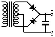
I always referred to it as Full Wave but from that linked site: "Beginners sometimes call the two-phase rectifier a 'full-wave rectifier'. This is wrong.". (although I see that their image filename is actually labelled 'full-wave'. A bit contradictory tbh).
Last edited:
Two-phase (also known as biphase) is an example of fullwave rectification. A bridge is another example of fullwave. I would say that 'two-phase' is the circuit; 'fullwave' is the result. As I said, two-phase was used during the valve era. There is less need for it now. It is less efficient than a bridge in the way it uses the transformer.
Hammond calls two diodes and a centre tap "Full Wave" as opposed to "Full Wave Bridge". http://www.hammondmfg.com/pdf/5c007.pdf
FWIW I use 450V 3300uF for my amplifiers. They were surplus and cheap, and the added capacitance allows me to use a lower value dropping resistor (24R/20W). However, I also run 300V at more than 500mA, so it's useful for loud dynamic passages. The power tubes idle at 120mA but peak at 700mA!
FWIW I use 450V 3300uF for my amplifiers. They were surplus and cheap, and the added capacitance allows me to use a lower value dropping resistor (24R/20W). However, I also run 300V at more than 500mA, so it's useful for loud dynamic passages. The power tubes idle at 120mA but peak at 700mA!
Hammond calls two diodes and a centre tap "Full Wave" as opposed to "Full Wave Bridge". http://www.hammondmfg.com/pdf/5c007.pdf
FWIW I use 450V 3300uF for my amplifiers. They were surplus and cheap, and the added capacitance allows me to use a lower value dropping resistor (24R/20W). However, I also run 300V at more than 500mA, so it's useful for loud dynamic passages. The power tubes idle at 120mA but peak at 700mA!
I only need 100ma 300vDC I was thinking of using 0 and 213v polar. What would be a design for a 300vdc rectifier using the 1 milifarad capacitor.? what resistance would I need in parallel to the cap?
I was thinking on putting 10-100 uf caps in parallel with alll 4 diodes as well
Two-phase (also known as biphase) is an example of fullwave rectification. A bridge is another example of fullwave. I would say that 'two-phase' is the circuit; 'fullwave' is the result. As I said, two-phase was used during the valve era. There is less need for it now. It is less efficient than a bridge in the way it uses the transformer.
Does it have less ripple to use a center tapped trafo than using a diode bridge and a polar trafo?
If you are using semiconductor rectifiers then there is no advantage in using 'two-phase' - that was used for valve rectifiers. A bridge is fine, and will make better use of the transformer capabilities.
Have you actually designed the PSU? You seem to be talking about bells and whistles already but I see no sign of the engine yet. The usual order is requirements -> draft design -> check design -> refine design -> order parts -> build it -> debug it -> adjust it You seem to be ordering parts already. What is your ripple specification ('as low as possible' is a wish, not a specification), for example?
I have a trafo maker who can make whatever I order. Aiming to get 300V DC and might order the trafo to 213 volts polar so that it rectifies to 300v. Is 213 and 0 correct for the trafo? The circuit demands 100ma and I want ripple to be as low as possible, I already have the milifarad caps and I bought them to reduce ripple as much as possible.
Hoping to use them, just need a rectifier design. I might also put small caps in parallel with all 4 diodes.
If you are using semiconductor rectifiers then there is no advantage in using 'two-phase' - that was used for valve rectifiers. A bridge is fine, and will make better use of the transformer capabilities.
Have you actually designed the PSU? You seem to be talking about bells and whistles already but I see no sign of the engine yet. The usual order is requirements -> draft design -> check design -> refine design -> order parts -> build it -> debug it -> adjust it You seem to be ordering parts already. What is your ripple specification ('as low as possible' is a wish, not a specification), for example?
I calculated out around 1v ripple using a 1 milifarad cap at 50hz 300Vdc. Thought that seems rather flat and a great value. I am ordering the trafo to supply 300Vdc @100ma. Looking for a good filter design
check this out. Is that a possibility to use for a supply? Vicor FARM1T21 Filter Autoranging Rectifier Module / AC to DC 300V 500/750W | eBay
Gosh! I can see the difference bigtime. I have one nice looking choke and it measures out at 3 ohms. What is that program? Sorry, I forgot to ask why the capacitors have resistance values next to them... Is that another resistor in parallel with each cap? EL84 PP Push-Pull amplifier, assembled PCB w autobias, tubes incl, 2ch. (2 PCBs) | eBay
That is the unit. there are four pics with the schematic at the link
Ok. That starts with 240v through a diode bridge to get around 300V. Why not the usual multiplying by root 2? I know there is a one volt drop per diode. I will go for a crc filter. I saw one using a milifarad and a 500 microfarad in parallel with a resistor in between. for 100ma that will produce inrush currents and best to abandon that idea, going for a crc with 2 100uf caps? Is 100 or 200uf the sweet spot?
Can I use a 1uf-10uf capacitor in parallel with each diode in the bridge? Then 2 100-200mf caps in a crc filter? I have seen that design before and it looked interesting.
hmm I just found a fullwave center tappped filter desifn that uses both windings all the time Linear Power Supply Design figure 6 If I used that fullwave center tapped design in fig 6, it would allow me to place 2 1mf in series, which would make 500uf. Then I could use something like 2 200ufs if I had the right resistance value for in between the caps.
I want to put caps across the diodes too. I hope not to throw away the caps but if they are bad, i will do it. I don't have a car and no fridge so I am not being an energy hog. Only the stereo and a laptop and a 100w tungsten plus an led in the bathroom. thats my primary consumption. No car
Imagine a nice amp made from solar panels and batteries. It would need no transformers for the DC. Solar is DC. The panels would need to be massive, probably a square meter minimum. That would depend on percent efficiency of the panels and listening time and battery efficiency. I know 100% would be 1000w/m and we are currently at 20% so 200w/m so a square meter panel operating at 8hrs per day will produce 1.6kwh per day
enough for eight hrs on a 200w system I wonder how DC from solar panels sounds after the battery, I also wonder about using something like a fgpa to divy exactly the correct amount of cells, probably 3v each and vary voltage with sunlight so may need to be connected by an array of diodes controlled by an fgpa.
It would have one diode at each of the four junctions between cells and then you could do things like put more cells in series as voltage production drops and put the cells in parallel as amperage drops and account for dark patches by immediately routing the current around covered cells, because in a series, one covered cell on panel can drop its output by 80%
Solar panels should have fgpas controlling diode arrays THat would let us use them without batteries
Last edited:
- Status
- This old topic is closed. If you want to reopen this topic, contact a moderator using the "Report Post" button.
- Home
- Amplifiers
- Power Supplies
- Need a design for a rectifier bridge producing 300V DC using a 450V 1000 micF 1mf cap