Hi,
Please bear with me, I'm a complete newbie on all these theory terms and conventions. Today I opened a Panasonic DVD-S35 that is malfunctioning (doesn't recognise the discs being inserted). I also downloaded the service manual. Just out of curiosity, not that I plan to even touch the mains or modify anything.
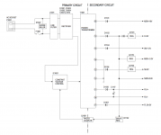
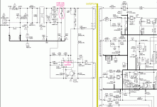
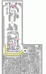
...And I found that the rectifiers come before the power transformer, see attach:

I found this quite shocking, but as I said I'm a complete illiterate on this ground. Is this really a weird design or common use of rectifiers?
Thank you
Please bear with me, I'm a complete newbie on all these theory terms and conventions. Today I opened a Panasonic DVD-S35 that is malfunctioning (doesn't recognise the discs being inserted). I also downloaded the service manual. Just out of curiosity, not that I plan to even touch the mains or modify anything.
...And I found that the rectifiers come before the power transformer, see attach:

I found this quite shocking, but as I said I'm a complete illiterate on this ground. Is this really a weird design or common use of rectifiers?
Thank you
This is a block diagram of a SMPS, not a classic liner one.
See here. Switched-mode power supply - Wikipedia
See here. Switched-mode power supply - Wikipedia
Last edited:
Yep, as just said by thimios, this is not a traditional transformer but an SMPS. The overall idea here is to rectify the net-voltage and then "chop" this primary voltage to a high frequency AC, which is then transformed by a smaller transformer to a plurality of secondary voltages.
Because the frequency is higher, the transformer can be smaller.
"Power transformer" is not a well chosen name for that block and you rightfully spotted it appears weird. You are on a good track.
Because the frequency is higher, the transformer can be smaller.
"Power transformer" is not a well chosen name for that block and you rightfully spotted it appears weird. You are on a good track.
Last edited:
T001 may in fact be the power transformer, if the “constant voltage control” happens to be a fly back or forward converter circuit. That is exactly how the transformer would be connected - between the HV bus and the collector of the power transistor (or IC). Most larger switchers are a full or half bridge, but stuff under 200W is often implemented in a simpler way with a single ended output.
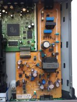
hey thank you so much guys. i’m sorry i missed this (key) info, what i understand is the “power transformer” in the scheme would be a small black box in the middle of the board. i can take a pic tomorrow if you’re interested, again out of curiosity. for what you all are suggesting, rectifiers before transformer is not a weird scheme in SMPSs, right? then question solved. thank you so much
Switch mode power supplies are becoming very popular. Mains transformers are getting to be expensive.
Switch mode just rectifies mains to peak mains voltage DC. Its then chopped and put through a high frequency (100KHz?) transformer. The output is rectified and smoothed. The output is sometimes fed back to the input for regulation purposes.
SMPS are very efficient especially if using power factor correction. You can sometimes get residual switching frequency on the output but that isn't insurmountable with filtering.
In laymans terms a flyback SMPS (that's the isolated type discussed here with the transformer instead of an inductor) effectively converts DC to AC by switching it on an off with a transistor, passes it through a transformer and rectifies the AC on the secondary side back into DC.
Because the transformer in an SMPS usually operates somewhere in the region of 100kHz instead 50Hz, it's inductance can be a lot lower than a typical mains transformer and that means that it can be a lot smaller, lighter and cheaper to manufacture.
The rectifier before the SMPS is purely because a flyback SMPS is a DC-to-DC converting device so the input must be DC. The simplest and cheapest way to achieve that is to straight rectify the 50Hz AC mains input. Since the SMPS can be designed to work at the resulting ~300V DC bus voltage, there is no need for a conventional 'step down' mains transformer in addition to the SMPS transformer.
Last edited:
- Status
- This old topic is closed. If you want to reopen this topic, contact a moderator using the "Report Post" button.
- Home
- Amplifiers
- Power Supplies
- rectifier before transformer?


