Hello
I'm looking at doing a change to my usual power supply startup that I use for the tube amps I build.
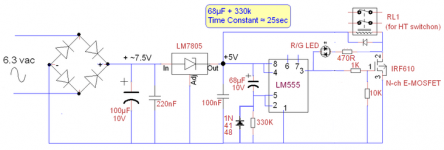
This is a simplified schematic

Background
My discussion here is around the bi-color LED.
The idea is for this LED to glow red during the warm-up phase, then turn green when the 555 switches the high voltage on.
In the past I've built this with a DPDT relay to act as a polarity reverser, but it occurred to me I could simplify this in the manner shown.
I'm kind-of in learn-by-doing mode here, so there's probably good reasons why this won't work, hence this post.
My reasoning is that we have a potential divider giving us +2.5V at the intersection of the two 150R resistors. The other side of which will be at 0V when the timer is in the off state, or +4.7V or near to it, when On.
Over the weekend I'll probably breadboard this, but thought I'd throw it on a post here in case anyone can see anything drastically wrong to save me the time...
I'm looking at doing a change to my usual power supply startup that I use for the tube amps I build.
This is a simplified schematic
Background
The idea of this power supply is to delay the switch-on of the high voltage long enough for the tubes to warm up. The relay shown turns on the high voltage. There's more circuitry around that relay to mitigate inrush, but I've omitted it because it's not relevant here.
I've built this circuit several times before. The Relay has a 5V coil voltage, hence the 7805. The MOSFET is there to mitigate the voltage drop through the 555. (It can work without it, but the coil only sees around 3v so it's marginal)
I've built this circuit several times before. The Relay has a 5V coil voltage, hence the 7805. The MOSFET is there to mitigate the voltage drop through the 555. (It can work without it, but the coil only sees around 3v so it's marginal)
My discussion here is around the bi-color LED.
The idea is for this LED to glow red during the warm-up phase, then turn green when the 555 switches the high voltage on.
In the past I've built this with a DPDT relay to act as a polarity reverser, but it occurred to me I could simplify this in the manner shown.
I'm kind-of in learn-by-doing mode here, so there's probably good reasons why this won't work, hence this post.
My reasoning is that we have a potential divider giving us +2.5V at the intersection of the two 150R resistors. The other side of which will be at 0V when the timer is in the off state, or +4.7V or near to it, when On.
Over the weekend I'll probably breadboard this, but thought I'd throw it on a post here in case anyone can see anything drastically wrong to save me the time...
Are you certain that the bi-colour LED is of the configuration you show ?
Yep - my stock of 2-color LEDs have 2 terminals, and they show red or green depending on polarity. It's why my previous polarity-reverser circuit relied on a DPDT relay with cross-connected contacts.
OK. It should work then but it will rely on the 555 output swinging fully to the rail or ground. If the 555 output swings say from 1v to 4v then the LED's may not light at all due to their forward volt drop. Its marginal. You could raise the 7805 a fraction (dead easy) if that were a problem.
The later 555 varieties (I would have to look up the exact part numbers) I believe will swing fully rail to rail and also support 100ma current.
The later 555 varieties (I would have to look up the exact part numbers) I believe will swing fully rail to rail and also support 100ma current.
OK. It should work then but it will rely on the 555 output swinging fully to the rail or ground. If the 555 output swings say from 1v to 4v then the LED's may not light at all due to their forward volt drop. Its marginal.
This is where I need to call on folks more experienced with 555s and MOSFETs than me... I've come up with the following (changes in the colored box)

In essence a complimentary pair of MOSFETs. N-Channel and P-Channel.
Idea being that when pin 3 of the 555 is high the N-MOSFET will turn on, and the P-MOSFET will turn off... connecting the left side of the LED to the negative rail.
When pin 3 is low, the N-MOSFET will turn off, the P-MOSFET will turn on, and the reverse will be true - the left pin of the LED will be connected to the positive rail.
This should negate any voltage drop through the 555
Bit of a self-defeating exercise though, the component count is now higher than using the DPDT relay...
So to my specific question... anyone see any reason this won't work? I'm a bit worried about the quiescent voltage at Pin 3 owing to all those 10K voltage reference resistors on the Gates of the MOSFETS.
Thanks to anyone taking the time to look this over.
consider a cmos inverter from the 555 output to the other side of the led+resistor instead of the voltage divider
Wow
")
I wasn't aware of the CMOS inverter circuit (I did say I wasn't so good at this stuff!)
But... after reading on it (thanks for the steer!) it turns out that it's exactly what I "invented" here.... am so glad my thinking is on track.
It still needs the Voltage Divider though... to give a voltage reference point half way between each rail.
Next job - breadboard it, then if it works, I'll make up a PCB design for it.
Don't know why I started down this track, my DPDT polarity reversing relay implementation works just fine, just felt I could improve it...
Why do you need the voltage divider? I meant, leave one side of the leds connected to the 555 output, and the other side to the inverter output. with an appropriate resistor in series (300 ohms?)
I would also suggest using a logic chip (4049) and connecting all six inverters in parallel, rather than discretes, but that's just me. I'm not sure why there are resistors in the gate circuit of your inverter's mosfets
I would also suggest using a logic chip (4049) and connecting all six inverters in parallel, rather than discretes, but that's just me. I'm not sure why there are resistors in the gate circuit of your inverter's mosfets
Why do you need the voltage divider? I meant, leave one side of the leds connected to the 555 output, and the other side to the inverter output.
Something like this?

(Appropriate series resistor, around 150R probably, to be added to the LED, omitted for simplicity)
Keep it simple
Mona
You'd have to experiment with that circuit. You might find that the 470R and the LED might pull enough current through the relay to activate it.
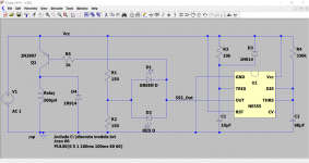
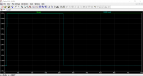
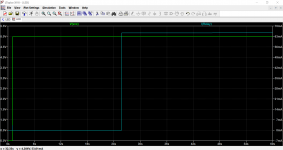
Here you go. The 555 output goes low after 25 seconds which also turns on the relay (not sure where your pin outs came from ).
If the 555 output doesn't quite make it to 5 volts (it should) then you will need a resistor across base and emitter to hold the transistor off.
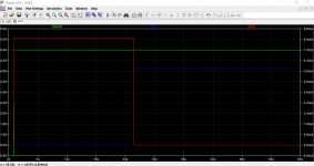
Third image shows the LED currents. They are unequal because of the differing turn on volts between red and green and so you will need to alter the two resistors to give desired brightness of each.
Final image shows the relay current.
).If the 555 output doesn't quite make it to 5 volts (it should) then you will need a resistor across base and emitter to hold the transistor off.
Third image shows the LED currents. They are unequal because of the differing turn on volts between red and green and so you will need to alter the two resistors to give desired brightness of each.
Final image shows the relay current.
Attachments
Relais for 5V has a resistance 50...100Ω, that leaves no more then 1volt for the relais, and even less with the LED in the circuit.So no problem.You'd have to experiment with that circuit. You might find that the 470R and the LED might pull enough current through the relay to activate it.
Mona
Keep it simple
Mona
That 470R needs to be 100R to get 1.7volt @ 20mA thru the LED
And in this design, I fear the flyback diode across the relay coil might interfere when the IC is in the OFF state.
100R is much to small, big chance the relais will go on immediately.But why 20mA ? modern LED's need only 2mA and 470R gives ~7mA.That 470R needs to be 100R to get 1.7volt @ 20mA thru the LED
And in this design, I fear the flyback diode across the relay coil might interfere when the IC is in the OFF state.
The flyback diode only prevents the voltage on the drain to go any higher then 5,6volt at turn-off.
Mona
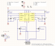
Sounds like something I designed last year for a tube amp, using a 556 to control two separate supplies to pre-amp and power-amp tubes.
I wasn't sure (at that point) how I would be controlling the HT power supplies so I built in two outputs per channel: one goes high (2V less than Vcc) and the other is an open-drain that clamps to ground when the timing period is up.
Vcc on mine is just the 12V heater supply but depending on the chip can be anywhere 5-15V.
Either of these can drive an LED, either high-output with resistor to ground, or Vcc through resistor to open-drain, which could work with either common-anode or common-cathode designs.
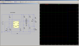
I understand that you've already bought the LEDs as the bidirectional type, but my circuit could still be wangled for that way. Just construct a resistor voltage-divider such that the current goes through the 'heat' LED on startup, then the FET shorts out a resistor to make the current go the other way through the 'run' LED. And seeing as I got bored, I simulated it on spice just to check that it would work.
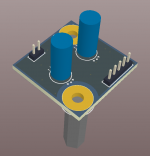
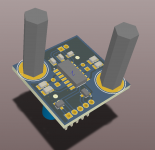
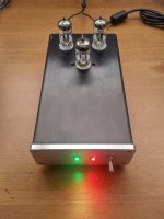
Or ditch the LEDs you've already bought, I think mine looks just as nice with both LEDs shining after the heatup phase instead of turning one off (they were some IP67 jobbies from Jaycar, I think you can get them in NZ). The photo is my turntable preamp, so only using 1-channel for the timer as it's all a single HT voltage.
And it's all on a PCB measuring 24x24mm with 2mm connectors, and still got two M3 holes for standoffs. I've got a few dozen left, want one?
(edit, grabbed the coil data for a random 5V relay here: https://docs-apac.rs-online.com/webdocs/14b2/0900766b814b2cde.pdf and chucked it into the simulation. It only picks up at 80% of 5V = 4V, so it definitely won't turn on until the mosfet does. Also, only ~7mA of current through the LEDs, adjust resistor values to taste...)
I wasn't sure (at that point) how I would be controlling the HT power supplies so I built in two outputs per channel: one goes high (2V less than Vcc) and the other is an open-drain that clamps to ground when the timing period is up.
Vcc on mine is just the 12V heater supply but depending on the chip can be anywhere 5-15V.
Either of these can drive an LED, either high-output with resistor to ground, or Vcc through resistor to open-drain, which could work with either common-anode or common-cathode designs.
I understand that you've already bought the LEDs as the bidirectional type, but my circuit could still be wangled for that way. Just construct a resistor voltage-divider such that the current goes through the 'heat' LED on startup, then the FET shorts out a resistor to make the current go the other way through the 'run' LED. And seeing as I got bored, I simulated it on spice just to check that it would work.
Or ditch the LEDs you've already bought, I think mine looks just as nice with both LEDs shining after the heatup phase instead of turning one off (they were some IP67 jobbies from Jaycar, I think you can get them in NZ). The photo is my turntable preamp, so only using 1-channel for the timer as it's all a single HT voltage.
And it's all on a PCB measuring 24x24mm with 2mm connectors, and still got two M3 holes for standoffs. I've got a few dozen left, want one?
(edit, grabbed the coil data for a random 5V relay here: https://docs-apac.rs-online.com/webdocs/14b2/0900766b814b2cde.pdf and chucked it into the simulation. It only picks up at 80% of 5V = 4V, so it definitely won't turn on until the mosfet does. Also, only ~7mA of current through the LEDs, adjust resistor values to taste...)
Attachments
Last edited:
- Status
- This old topic is closed. If you want to reopen this topic, contact a moderator using the "Report Post" button.
- Home
- Amplifiers
- Power Supplies
- PSU for tube amp - 555 timer delay turn on