I am a novice with DIY electronics. I ordered two of these boards to make a stereo amplifier. TDA7293 AC 12V 32V 100W Digital Audio Amplifier Single Channel AMP Board -in Integrated Circuits from Electronic Components & Supplies on Aliexpress.com | Alibaba Group
In the photo it shows to connect 32-0-32 dual AC transformer to a board. This would mean I would need two transformers and two mains sockets to power the the combined steroids amplfier right? Is there a way to use a single transformer to get good results or at least so I can use one mains socket to power the finished stereo amplifier?
In the photo it shows to connect 32-0-32 dual AC transformer to a board. This would mean I would need two transformers and two mains sockets to power the the combined steroids amplfier right? Is there a way to use a single transformer to get good results or at least so I can use one mains socket to power the finished stereo amplifier?
It means a transformer with either dual secondary's or a single secondary with a tapping in the centre. Both types are common and the most frequently used in audio applications.
Example:
https://cpc.farnell.com/multicomp/mcta160-18/160va-toroidal-2x18v/dp/FF01565
I would suggest something like an 18-0-18 for reliability.
(Also the TDA7293 is not a 'digital' amplifier but a traditional Class AB type. You will also need a suitable heatsink)
Example:
https://cpc.farnell.com/multicomp/mcta160-18/160va-toroidal-2x18v/dp/FF01565
I would suggest something like an 18-0-18 for reliability.
(Also the TDA7293 is not a 'digital' amplifier but a traditional Class AB type. You will also need a suitable heatsink)
It means a transformer with either dual secondary's or a single secondary with a tapping in the centre. Both types are common and the most frequently used in audio applications.
Example:
https://cpc.farnell.com/multicomp/mcta160-18/160va-toroidal-2x18v/dp/FF01565
I would suggest something like an 18-0-18 for reliability.
(Also the TDA7293 is not a 'digital' amplifier but a traditional Class AB type. You will also need a suitable heatsink)
I see. Would these provide 18-0-18 to both boards? Also since I want to get the maximum output, using 32-0-32 wouldn't be a problem would it?
Are you going to use them with 4 or 8 Ohm speakers? It has an influence on the supply voltage.
6 Ohm speakers for the time being.
I see. Would these provide 18-0-18 to both boards? Also since I want to get the maximum output, using 32-0-32 wouldn't be a problem would it?
The DC voltage will be 32v multiplied by root 2 and so that would give -/+45 volts DC. Also remember that the transformer voltage be higher than stated at low loading, and you also have to account for higher than specified mains voltage. So the 45 volts soon creeps up and that is asking for trouble.
The board has reservoir caps incorporated but these will never handle the full ripple current that delivering 100 watts rms would generate.
You have to be realistic.
Thanks for pointing all that. But the seller did take all that voltage increase into account when recommending the 32V AC power, I am guessing, partly due to ST rating TDA7293 as 120V (which may mean it can handle that volatage is my guess). Also I wanted to say a YouTuber johnaudiotech got 92 Watts using a 4ohm load using a similar board here YouTube which actually got my hopes up.
Its up to you whether you push it toward its limits ")
Delivering 100 wrms into 8ohms is serious stuff in terms of heat dissipation and power supply currents. 4 ohms and things get really tough.
That board only looks to have 2200uF reservoir caps. Those are going to see the voltage across them sag at full loading, perhaps giving as much as 8 volts ripple on the rail. The caps will also see massive charging pulses limited only by the power supply impedance... which will exceed the ripple current of the caps.
My advice is still to be realistic and aim for less. It will run much cooler and be far more reliable.
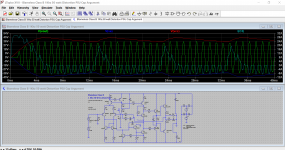
This shows a typical Class AB amp just like the TDA7293 chip.
Look how the power supply sags each half cycle of the transformer voltage. This means the amp can not deliver its full output. Notice how it clips as the supply sags. Also look just how high the charging current in the 2200uF reservoir cap is.
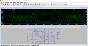
Second image is with more substantial 10,000uF caps which would be typically specified for such a high power design.
Look how the power supply sags each half cycle of the transformer voltage. This means the amp can not deliver its full output. Notice how it clips as the supply sags. Also look just how high the charging current in the 2200uF reservoir cap is.
Second image is with more substantial 10,000uF caps which would be typically specified for such a high power design.
Attachments
I support Mooly's comments. My guess is that your idle voltage will be close to +/-48V with standard net voltage.
The reason why I asked for the speaker impedance: The current limiter threshold is 6.5A (typical) for TDA7293 (page 5 of the datasheet). If you have a +/- 48V supply voltage and we leave 3V for output driver drop, The peak current will then be 45/6=7.5A, thus, exceeding the current limiter threshold. With 4 Ohm it will be significantly worse (you will even exceed the absolute maximum ratings,10A). Only with 8 Ohm, you will stay within limits.
The 120V you mention is non-operational (datasheet page 4).
Therefore, Mooly's advise makes a lot of sense. If you do not use 4 Ohm speakers, you may use a 2x22Vac transformer (2x33Vdc idle).
If you consider this an experiment concerning how much power you can get out of an TDA7293 and won't cry if it burns, 2x32Vac is the absolute maximum.
I have the same boards. One TDA7293 chip did not work for a start. Changing that chip and applying a few "mods" made them play well. I have never taken them further than +/- 37Vdc and only used 8 Ohm speakers.
Mooly is also fully right that 2200uF is far too little power decoupling with that output power. 6800uF-10000uF is more what you need, per rail and per board! Many forget that when you have invested in a powerful amplifier board, the power supply needs to be even more powerful and cost typically more than the amplifier board.
Last edited:
I'd recommend following fauxfrench's recommendation: 32v dc per rail is about as high as I'd go on a 7293, before that sucker is going to get too hot. You're not really buying yourself much extra power by goosing the rails higher. The chip is definitely not rated for 33 vac/ 47vdc!
Assume a volt loss across your rectifier, and you get something like 23v. 22v is a more common transformer rating so there you go.
Assume a volt loss across your rectifier, and you get something like 23v. 22v is a more common transformer rating so there you go.
Its up to you whether you push it toward its limits
Delivering 100 wrms into 8ohms is serious stuff in terms of heat dissipation and power supply currents. 4 ohms and things get really tough.
That board only looks to have 2200uF reservoir caps. Those are going to see the voltage across them sag at full loading, perhaps giving as much as 8 volts ripple on the rail. The caps will also see massive charging pulses limited only by the power supply impedance... which will exceed the ripple current of the caps.
My advice is still to be realistic and aim for less. It will run much cooler and be far more reliable.
Thanks for all the input. I was looking for a 100w or close to 100w chip amp that can provide the kind of quality TDA7293 and something that's also cheap. It's a bit off topic but do you have any suggestions?
I support Mooly's comments. My guess is that your idle voltage will be close to +/-48V with standard net voltage.
The reason why I asked for the speaker impedance: The current limiter threshold is 6.5A (typical) for TDA7293 (page 5 of the datasheet). If you have a +/- 48V supply voltage and we leave 3V for output driver drop, The peak current will then be 45/6=7.5A, thus, exceeding the current limiter threshold. With 4 Ohm it will be significantly worse (you will even exceed the absolute maximum ratings,10A). Only with 8 Ohm, you will stay within limits.
The 120V you mention is non-operational (datasheet page 4).
Therefore, Mooly's advise makes a lot of sense. If you do not use 4 Ohm speakers, you may use a 2x22Vac transformer (2x33Vdc idle).
If you consider this an experiment concerning how much power you can get out of an TDA7293 and won't cry if it burns, 2x32Vac is the absolute maximum.
I have the same boards. One TDA7293 chip did not work for a start. Changing that chip and applying a few "mods" made them play well. I have never taken them further than +/- 37Vdc and only used 8 Ohm speakers.
Mooly is also fully right that 2200uF is far too little power decoupling with that output power. 6800uF-10000uF is more what you need, per rail and per board! Many forget that when you have invested in a powerful amplifier board, the power supply needs to be even more powerful and cost typically more than the amplifier board.
Thanks for the input. It may sound stupid, but what happens if the current limiter threshold is exceeded? I am kind of unsure about am saying but isn't 45 volts the idle voltage? Would 6.5A current output be a problem even so? This video YouTube shows Johnaudiotech using 32V into 4 ohms and getting a clean output I think. Please tell me what you think.
I'd recommend following fauxfrench's recommendation: 32v dc per rail is about as high as I'd go on a 7293, before that sucker is going to get too hot. You're not really buying yourself much extra power by goosing the rails higher. The chip is definitely not rated for 33 vac/ 47vdc!
Assume a volt loss across your rectifier, and you get something like 23v. 22v is a more common transformer rating so there you go.
Thanks for the input. So 32 vac + 6ohms load is undoable? fauxfrench recommends not going with 6ohm speakers if use 32vac.
Thanks for all the input. I was looking for a 100w or close to 100w chip amp that can provide the kind of quality TDA7293 and something that's also cheap. It's a bit off topic but do you have any suggestions?
I can't think of anything as cheap as this, or as simple to build as this is.
Why not set your goals a little lower. The subjective difference in loudness between a 50 and 100watt amp is very small. Do you actually need this figure of 100 watts capability ?
You could make a separate power supply (bridge and two larger can type reservoir caps) and feed two TDA7293's from that. The DC voltage would feed straight into your boards and onto the caps already on the board. The rectifier on the board would be left in place but it would be redundant and not do anything. The 2200uF caps would be the equivalent of local decoupling with the larger off board caps providing a smooth supply.
A 25-0-25 transformer would produce a total of -/+35 volts DC and that should allow an output of almost 60 watts rms into 8 ohms.
Fwiw, most ordinary listening takes place at just a few watts (at the very most) and typically can be around 1 watt or less.
Thanks for the input. It may sound stupid, but what happens if the current limiter threshold is exceeded? I am kind of unsure about am saying but isn't 45 volts the idle voltage? Would 6.5A current output be a problem even so? This video YouTube shows Johnaudiotech using 32V into 4 ohms and getting a clean output I think. Please tell me what you think.
If the current limiter is invoked it will create a lot of distortion because the current limiter hardly can "clip" as clean as voltage clipping so I would expect more harmonics.
My experience is that you get around 1.5 times the nominal AC voltage when rectified and in idle mode. The reason is that the 32Vac is with nominal loading. The output voltage increases when not loaded.
Johnaudiotech takes it to the limit with a huge heatsink and a regulated power supply. He is probably an experienced guy with that equipment. As you have noticed, he uses a maximum of 32Vdc. No 45-48Vdc. We give you advise and our advise to you, as a less experienced DIYer, is to be a bit prudent and run less risk with the lifetime of the amplifier.
A 2x22Vac transformer leaves a rectified idle voltage around 2x33Vdc. In the end, it is your choice how much risk you like to take for an increase in output power.
Last edited:
Fully agree with above written excellent advice and add a bit on how to read that datasheet.
Which doesn´t actually *lie*, everything it says is truth, but please consider all warnings, caveats, "buyer beware" and "YMMV" type stuff :
Datasheet:
https://www.st.com/resource/en/datasheet/cd00001887.pdf
1) Prominently displayed on header:
2) just 2 lines below that, in slightly smaller letter size:
3) another 2 lines below that:
b) And the first time they speak about it putting out some power, they again downgrade voltage rails to +/-40V , go figure.
4) and later,once you do the Math on output current capabilities, which are limited for safety,you will downgrade real output power even more.
Besides, plain limiting by hitting rails, which will happen somewhat earlier if you lower rail voltage, does not sound as bad as clipping created by foldback current limiting/short circuit protection built into this amplifier.
They look about the same when driving purely resistive loads, but when driving highly reactive loudspeakers they "trigger early" and produce horrible buzzing sound.
So in the real world, using the apparently "reduced" rail voltages suggested above (+/-32V) will actually provide the maximum available power, if you want it to be clean and driving real World speakers.
5) besides datasheets, lookat it from another side:
* same case size LM3886 is rated 50/60W RMS into 8/4 ohm loads, is famous for its reliability and high quality sound and is still very popular, even if it´s quite older, while TDA729x, which "should" have replaced it in full, actually did not, got a reputation of unreliability, backed by user experience, so much so that a few established MI amplifier manufacturers have been "burnt" by trusting its promise:
Fishman used it as a 100W power amp in one of its Loudbox Acoustic Guitar amplifiers: it fails often.
Marshall used it a lot, from 100W MG Guitar amps to MF350 350W RMS monsters, using 4 of them in bridged parallel configuration: they fail so much that they had to offer a user-replaceable plug in (no soldering involved) miniboard so they could be "repaired at home", go figure:
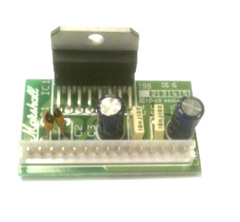
In a nutshell: that small case, exactly the same as 2 x TO220 cases side by side, can safely dissipate heat produced by a 50/60W amplifier, experience has shown it is not enough for 80/100W ones, so it´s prudent to use it within safe limits.
Yes, you probably *can* pull 100W from one of them ... for a short time and if you are not terribly worried about distortion and reliability, but ... why bother?
Want more power out of a "chipamp"?
Have a look at Sanken or Sanyo STK modules ... only problem is that they are much larger, more expensive ... and not *really* chipamps but hybrid modules, which can be described as a "Factory packaged ... discrete amplifiers .... "
See it by yourself:

they even have not-so-tiny PCBs inside
Which doesn´t actually *lie*, everything it says is truth, but please consider all warnings, caveats, "buyer beware" and "YMMV" type stuff :
Datasheet:
https://www.st.com/resource/en/datasheet/cd00001887.pdf
1) Prominently displayed on header:
120-volt, 100-watt, DMOS audio amplifier
2) just 2 lines below that, in slightly smaller letter size:
Hey!!!! what happened to "120V" ????Very high operating voltage range (±50 V)
3) another 2 lines below that:
a) 100W @ 10% distortion which is a quite clipped signal amounts to about 80W unclipped ... so no "real" 100W to begin with.High output power (100 W into 8 Ω
@ THD =10%, with VS = ±40 V)
b) And the first time they speak about it putting out some power, they again downgrade voltage rails to +/-40V , go figure.
4) and later,once you do the Math on output current capabilities, which are limited for safety,you will downgrade real output power even more.
Besides, plain limiting by hitting rails, which will happen somewhat earlier if you lower rail voltage, does not sound as bad as clipping created by foldback current limiting/short circuit protection built into this amplifier.
They look about the same when driving purely resistive loads, but when driving highly reactive loudspeakers they "trigger early" and produce horrible buzzing sound.
So in the real world, using the apparently "reduced" rail voltages suggested above (+/-32V) will actually provide the maximum available power, if you want it to be clean and driving real World speakers.
5) besides datasheets, lookat it from another side:
* same case size LM3886 is rated 50/60W RMS into 8/4 ohm loads, is famous for its reliability and high quality sound and is still very popular, even if it´s quite older, while TDA729x, which "should" have replaced it in full, actually did not, got a reputation of unreliability, backed by user experience, so much so that a few established MI amplifier manufacturers have been "burnt" by trusting its promise:
Fishman used it as a 100W power amp in one of its Loudbox Acoustic Guitar amplifiers: it fails often.
Marshall used it a lot, from 100W MG Guitar amps to MF350 350W RMS monsters, using 4 of them in bridged parallel configuration: they fail so much that they had to offer a user-replaceable plug in (no soldering involved) miniboard so they could be "repaired at home", go figure:
In a nutshell: that small case, exactly the same as 2 x TO220 cases side by side, can safely dissipate heat produced by a 50/60W amplifier, experience has shown it is not enough for 80/100W ones, so it´s prudent to use it within safe limits.
Yes, you probably *can* pull 100W from one of them ... for a short time and if you are not terribly worried about distortion and reliability, but ... why bother?
Want more power out of a "chipamp"?
Have a look at Sanken or Sanyo STK modules ... only problem is that they are much larger, more expensive ... and not *really* chipamps but hybrid modules, which can be described as a "Factory packaged ... discrete amplifiers .... "
See it by yourself:
they even have not-so-tiny PCBs inside
I am guessing, partly due to ST rating TDA7293 as 120V (which may mean it can handle that volatage is my guess)..
Be very careful with spec max volts for chip amps as I have seen it specified at a high voltage but with the input shorted !!!!!
A bit stupid spec-ing for the input shorted when you want it to function as a power amp.
I wont run my 7294's off anything over +/- 35 volts DC.
I can't think of anything as cheap as this, or as simple to build as this is.
Why not set your goals a little lower. The subjective difference in loudness between a 50 and 100watt amp is very small. Do you actually need this figure of 100 watts capability ?
You could make a separate power supply (bridge and two larger can type reservoir caps) and feed two TDA7293's from that. The DC voltage would feed straight into your boards and onto the caps already on the board. The rectifier on the board would be left in place but it would be redundant and not do anything. The 2200uF caps would be the equivalent of local decoupling with the larger off board caps providing a smooth supply.
A 25-0-25 transformer would produce a total of -/+35 volts DC and that should allow an output of almost 60 watts rms into 8 ohms.
Fwiw, most ordinary listening takes place at just a few watts (at the very most) and typically can be around 1 watt or less.
Ah I see. So let's look at the situation using this perspective. Using an external DC conversion will have me stop worrying about idle voltage right? I am new to using transformers and somewhere in a customer review I read a DC supply won't work with this board, again maybe that's not the whole picture. 35V would allow me to use the 6 ohm speakers I have too I believe since they won't exceed the 6.5 current limiter in the data sheet. So it seems I would be safe with 6 ohm speakers in this setting. I would love to try out this but I lack all the knowledge of doing this.
If the current limiter is invoked it will create a lot of distortion because the current limiter hardly can "clip" as clean as voltage clipping so I would expect more harmonics.
My experience is that you get around 1.5 times the nominal AC voltage when rectified and in idle mode. The reason is that the 32Vac is with nominal loading. The output voltage increases when not loaded.
Johnaudiotech takes it to the limit with a huge heatsink and a regulated power supply. He is probably an experienced guy with that equipment. As you have noticed, he uses a maximum of 32Vdc. No 45-48Vdc. We give you advise and our advise to you, as a less experienced DIYer, is to be a bit prudent and run less risk with the lifetime of the amplifier.
A 2x22Vac transformer leaves a rectified idle voltage around 2x33Vdc. In the end, it is your choice how much risk you like to take for an increase in output power.
This is probably what I will do. Just out of curiosity, what active voltage may I expect with 2x22VAC? is it 22x√2 ? The active voltage and idle don't seem very different in this case.
- Home
- Amplifiers
- Power Supplies
- Need solution for powering two TDA 7293 boards