Cap mults are built with MOSFETs operating as source followers. Hence the gain is close to unity (0dB).
I'd say you'd be better off paying attention to current and power dissipation capability of the FET. Oh and threshold voltage - lower is better as then you'll need lower voltage overhead.
I'd say you'd be better off paying attention to current and power dissipation capability of the FET. Oh and threshold voltage - lower is better as then you'll need lower voltage overhead.
I've not looked at the video but from a quick search at Mouser for TO220 style N-channel FETs, this one looks suitable. Its only 30V rated though but if you need no more than 10V that's fine.
STP200N3LL STMicroelectronics | Mouser
STP200N3LL STMicroelectronics | Mouser
I am not sure that -I do understand, am new in electronic.
Your plan has the ripple reduction of 10K against 100uFd, without the large voltage drop of a 10K resistor into a heavy load.
DO you know enough electricity to compute this voltage drop for your load? (Quite often we do not really need a multiplier; large caps are inexpensive and can give good ripple reduction even with small series resistors.)
The ripple reduction (either way) is the ratio of ripple frequency to the R-C cutoff frequency. With time you learn to do this in your head; it is faster than going on-line to find an R-C calculator. I "know" 100 Ohms and 100uFd is 17Hz. So 100X the R must make it 0.17Hz. 100Hz/0.17Hz is 588:1 reduction.
Your proposed 120 Amp MOSFET has low internal resistance at many-many Amps. That's a good sign, but note there is NO data for currents in the milli-Amp range where most audio works. On-resistance drops from 120A(!) to 20A (Fig7) but it could rise at lower current. The transconductance of ALL active devices drops with current. This part will probably work, and the price is small.
I chose such a high amperage FET (even though its not needed) because it showed up near the top of the sort pile when I asked to sort on threshold voltage. Looks like this one should only need about 2V on the gate. The downside of such a large die FET would normally be price (but this one's quite cheap) and parasitic capacitances (about 2nF with 2V across).
From what I can understand in the video, the goal is to simulate a giant capacitor to eliminate ripples. As I understand a 10kO is not really high and yes maybe the capacitor are a bit big but the result shuld be as if you had a capacitor with the same size as cap * fet-gain.
> as if you had a capacitor with the same size as cap * fet-gain.
That is a fair simplification for a BIPOLAR junction transistor.
The BJT Base sucks current, which limits the "multiplication".
The MOSFET Gate sucks "NO!" current. In that sense the "gain" is "infinite". As with all simple infinities, in real life the parasitics become dominant. For the MOSFET, ON-resistance certainly matters. abraxalito's suggestion gives way-way-low Ron for only a dollar.
MOSFETs are fairly big capacitors. There will be shoot-through Drain-Source into the load. You want a heavy passive cap on the Source to absorb this.
The calculated 588:1 reduction applies only if the parasitic resistance around the R-C loop can be held to 1/588 of the total (dubious with real parts); and only as long as the MOSFET stays in its linear range. With a 2V threshold, 3V peak ripple will break-through, so the feed to this should be clean to <1V.
Yes if you use a BJT, you have to use a smaller resistance so you do not go under minimum voltage for the base. Since the FET do not use current, you can in theory use any size of resistor you want. And by using a FET can you "multiply" the cap's value and thereby get same effect as a several Farad cap would give.
What CAP and FET would you suggest me to use?
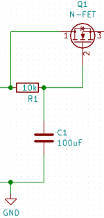
Here are my whole circuit
What CAP and FET would you suggest me to use?
Here are my whole circuit
Attachments
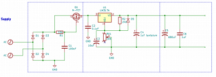
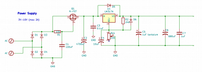
You're missing a reservoir cap directly after the bridge rectifier (D1-D4). You should have something around 3300uF there, depending on how much current you're taking through the LM317.
If you want to protect the reg against output short of the FET stage, add D6 with cathode to LM317 pin3, anode to pin2.
If you want to protect the reg against output short of the FET stage, add D6 with cathode to LM317 pin3, anode to pin2.
It is the transconductance (gm) of the FET that you need to know. At low frequencies the small-signal output impedance of the FET will be about 1/gm ohms but won’t get any smaller than the FETs source resistance. At high frequencies the capacitances of the FET become significant and the impedance becomes very complicated to calculate.I am building a capacitor multiplier with:
10kOhm
100uF
and a N-mosfet, I am not sure wich one.
What I need is to know is how to calculate the gain in a N-FET?
Thanks in advance!")
The tricky thing is that the gm depends on Id in a big way. You can find this relationship in the data sheet.
Having seen the more complete application I would agree that the FET isn't the best one in this circuit. Reason being - LM317 has reasonable LF ripple rejection but sucks badly at higher frequencies. Those higher freqs will be let through by the FET's parasitic capacitances.
For an overall better solution I'd use an LC filter instead of the cap mult, its a better complement to the foibles of the LM317 in that it'll have good HF rejection.
This is assuming all along you're aiming for the best line rejection you can get.
For an overall better solution I'd use an LC filter instead of the cap mult, its a better complement to the foibles of the LM317 in that it'll have good HF rejection.
This is assuming all along you're aiming for the best line rejection you can get.
I was thinking of adding a HF filter, but was concerned about the voltage drop.
The cap-multi do not have any voltage drop but do still filter HF, as I thought I did understand it, am I completely wrong?
Sorry for all my questions but have no lab yet, am trying to get money to a beginner scope
The cap-multi do not have any voltage drop but do still filter HF, as I thought I did understand it, am I completely wrong?
Sorry for all my questions but have no lab yet, am trying to get money to a beginner scope
A couple of obvious things from the schematic - C2 is in the wrong place, it needs to be before R1. And D5 is backwards. You don't need two 1uF caps on the output incidentally, just one will be sufficient.
The cap multi certainly does have a voltage drop - its output will be at least 2V lower than the input (assuming the same FET with the 2V gate threshold voltage). If you're running at 1A you could afford a 2ohm ESR inductor in its place for the same drop.
The cap multi certainly does have a voltage drop - its output will be at least 2V lower than the input (assuming the same FET with the 2V gate threshold voltage). If you're running at 1A you could afford a 2ohm ESR inductor in its place for the same drop.
Last edited:
C2 is there to hold the voltage within the working range of the cap mult while the mains is below its peak value. If its omitted the cap multi cannot provide the benefits you're looking for as it can't output a voltage higher than its input - its input voltage goes away 100 times every second.
- Status
- This old topic is closed. If you want to reopen this topic, contact a moderator using the "Report Post" button.
- Home
- Amplifiers
- Power Supplies
- Calculate MOSFET gain?