Here's a FET with much lower parasitic capacitances. Its disadvantage is its going to need almost 6V on the gate to get 1A out so you'll need more input volts and a bigger FET heatsink.
FDU6N25 ON Semiconductor / Fairchild | Mouser 香港
It is a bit cheaper though.
FDU6N25 ON Semiconductor / Fairchild | Mouser 香港
It is a bit cheaper though.
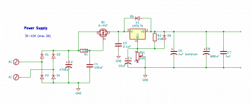
Perhaps the thing which the OP has failed to grasp is that in a so-called 'capacitance multiplier' no multiplication of capacitance value takes place. It is simply a first-order low pass filter plus buffer. You still need a reservoir capacitor, and that still needs to be big enough to avoid significant voltage rail droop. All the capacitance multiplier gets you is reduced ripple with a better balance of voltage drop vs. ripple.
DF96 I did understand that, what is really happens is that the resistor reduces the amount of current to the FET but I did not understand that I did need a reservoir capacitor so thanks to your all's answers I did learn that.
My goal as is abraxalito said, to get as clean power as possible, completely without ripples and noise of any kind (know that it is not possible).
My goal as is abraxalito said, to get as clean power as possible, completely without ripples and noise of any kind (know that it is not possible).
Thank you wary much!!
Just so I can learn a bit, you looked for power dissipation and voltage treshold, did you judge the component by other things also?
I selected a through-hole mounting requirement along with N-channel, single FET per package, silicon based and below 600V operation. Then I sorted based on gate charge to get the smaller die devices at the top of the pile.
No, what really happens is that the resistor reduces the amount of current to the capacitor.FriedMule said:what is really happens is that the resistor reduces the amount of current to the FET
To get clean power you need to concentrate on grounding rather than smoothing, as that is the area which newbies are most likely to get wrong. Why not keep your first PSU very simple and then build a better one later?
abraxalito okay thanks for explaining your metode")
DF96 sorry yes that was what I did want to write, but only reason for I know all that, is the video from EEVBlog.
I have designed simple psu's before but this time I do want to try to design a better power supply!
Please do tell me about grounding
DF96 sorry yes that was what I did want to write, but only reason for I know all that, is the video from EEVBlog.
I have designed simple psu's before but this time I do want to try to design a better power supply!
Please do tell me about grounding
Yes sorry, I know a little but for the most time, when I know something, I do often not know the right word for it.
But one thing I do know almost nothing about is shielding and grounding, I know that a star grounding often is far better then several or several goint to the same track / cable and then to ground.
But I do really not know how to ground my circuit, so that it is only a "one way street", thinking of all the noise a ground can have.
- Status
- This old topic is closed. If you want to reopen this topic, contact a moderator using the "Report Post" button.
- Home
- Amplifiers
- Power Supplies
- Calculate MOSFET gain?