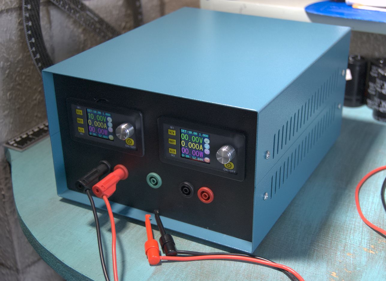
I used to use a linear bench PSU, but now it's 50 years old, even though it still works fine, I decided that it was about time to replace it with a fancy new one. So that it would be light and efficient, I got some DPS5005 switching regulators, which are rather nice devices capable of 0-50V output at 5A, with a nice display and the potential to be controlled by a PC or phone. To feed those, I got some 48V 6.5A switching PSUs (which have a small adjustment range, allowing them to be adjusted to 52V to fully cover the range of the regulators). I then stuck it all into a box.
I expected there to be some noise generated by these, but there was rather a lot more than expected. Some of it comes from the regulators, but most of it comes from the PSUs. The first thing I tried was an LC filter on the output, but no matter how big I made it, it had no effect on the noise at all. That meant that it must not be differential-mode noise, but common-mode instead.
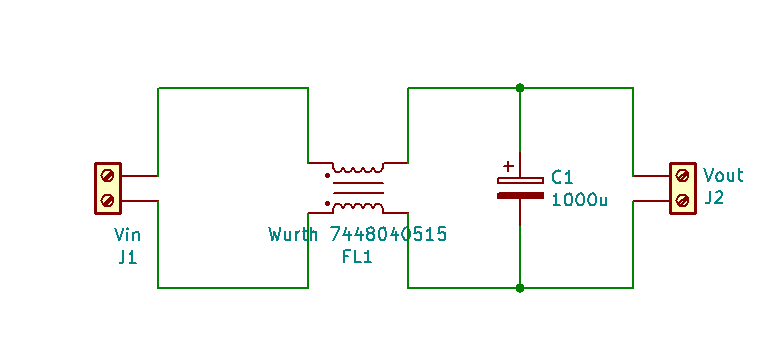
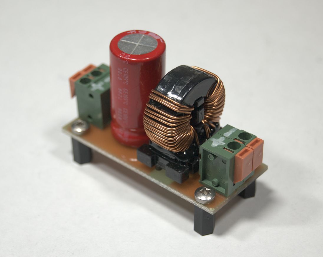
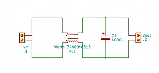
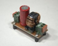
Common-mode noise can be generated by switching PSUs due to parasitic capacitance between the primary and secondary of the transformer, and between the switch and earth. Since I couldn't do much about either of those, I had to filter it out afterwards using common-mode chokes. I got some large 15mH 5A chokes, as larger ones offer better attenuation at the lower frequencies that are a problem here. They are rather expensive though; smaller chokes can be much cheaper and can still give a useful amount of attenuation.
Confident that the problem was solved, I fitted the filters inside the case and measured again, only to find that not only were the filters no longer filtering effectively, there were actually some completely new frequencies of noise present. This was supposed to be a simple project, being no more than putting some off-the-shelf parts into a case, yet somehow it was taking an excessive amount of time...

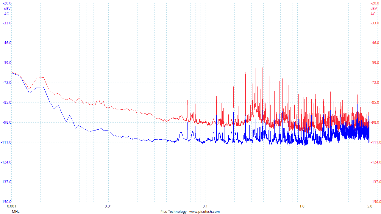
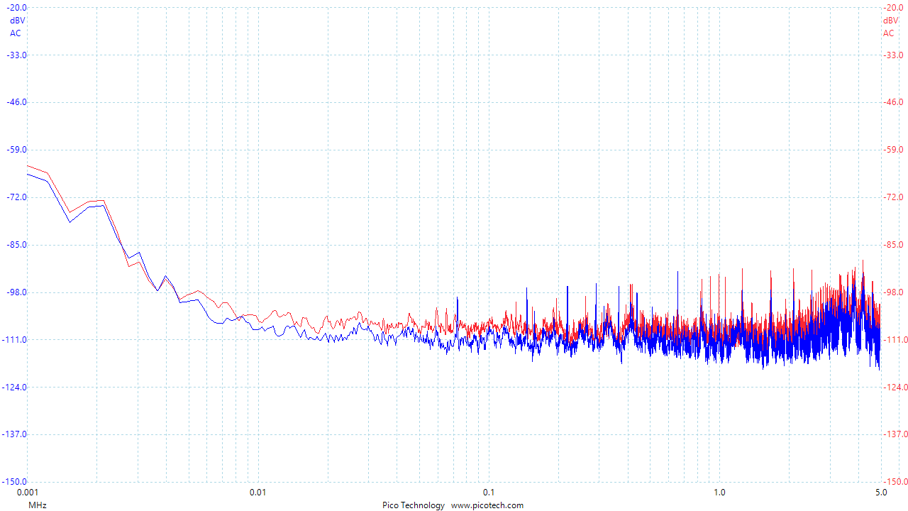
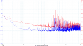
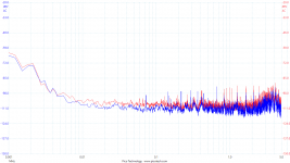
Blue is with a filter fitted. Red is the other channel with no filter, for comparison.
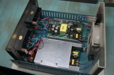
By waving the end of my scope probe around inside the case, and moving the regulator and filters around, I determined that noise was being radiated from the PSUs and picked up by the wiring. There are multiple possible solutions to that - I chose to shield the PSUs by covering them with aluminium.

There's another piece of the shield that goes over the mains end which I have removed for this photo so you can better see how it is assembled from bits of aluminium angle.
Blue is with both filter and shield fitted. Red is an unfiltered channel.
With shields and filters fitted to both channels, it looks a lot more respectable.
The peak at around 330kHz, presumably the switching frequency, is gone completely. There are still some other peaks, but most of those remain present even if I switch the whole PSU off, indicating that they are external noise, so adding more filtering wouldn't help. It's good enough for most purposes now. If I want it to be quieter, I will have to add a separate linear post-regulator.
I expected there to be some noise generated by these, but there was rather a lot more than expected. Some of it comes from the regulators, but most of it comes from the PSUs. The first thing I tried was an LC filter on the output, but no matter how big I made it, it had no effect on the noise at all. That meant that it must not be differential-mode noise, but common-mode instead.
Common-mode noise can be generated by switching PSUs due to parasitic capacitance between the primary and secondary of the transformer, and between the switch and earth. Since I couldn't do much about either of those, I had to filter it out afterwards using common-mode chokes. I got some large 15mH 5A chokes, as larger ones offer better attenuation at the lower frequencies that are a problem here. They are rather expensive though; smaller chokes can be much cheaper and can still give a useful amount of attenuation.
Confident that the problem was solved, I fitted the filters inside the case and measured again, only to find that not only were the filters no longer filtering effectively, there were actually some completely new frequencies of noise present. This was supposed to be a simple project, being no more than putting some off-the-shelf parts into a case, yet somehow it was taking an excessive amount of time...
Blue is with a filter fitted. Red is the other channel with no filter, for comparison.
By waving the end of my scope probe around inside the case, and moving the regulator and filters around, I determined that noise was being radiated from the PSUs and picked up by the wiring. There are multiple possible solutions to that - I chose to shield the PSUs by covering them with aluminium.
There's another piece of the shield that goes over the mains end which I have removed for this photo so you can better see how it is assembled from bits of aluminium angle.
Blue is with both filter and shield fitted. Red is an unfiltered channel.
With shields and filters fitted to both channels, it looks a lot more respectable.
The peak at around 330kHz, presumably the switching frequency, is gone completely. There are still some other peaks, but most of those remain present even if I switch the whole PSU off, indicating that they are external noise, so adding more filtering wouldn't help. It's good enough for most purposes now. If I want it to be quieter, I will have to add a separate linear post-regulator.
Attachments
-
 Filter schematic.png1.6 KB · Views: 555
 -
 Filter.jpg63.9 KB · Views: 552
 -
 nothing (Red), filter only (blue).png15.8 KB · Views: 540
 -
 One side shielded.jpg198.6 KB · Views: 557
 -
 nothing (red), filter + shield (blue).png15.2 KB · Views: 550
 -
 filter + shield (both).png14.4 KB · Views: 523
 -
 Front.jpg134.4 KB · Views: 548
Last edited:
Also -- did you filter the line coming into the switcher? (The noise goes out both ends!) A 1,000uF capacitor at 300kHz might not be 1,000u -- put 1uF/250V polypro in parallel.
Looks like you used OEM switchers -- it's hard to get in there and replace the diodes, or snub those already in place.
Looks like you used OEM switchers -- it's hard to get in there and replace the diodes, or snub those already in place.
In the photo of the inside of thew case, you can just about see on the right hand side that each PSU has a common mode choke in it (with a blob of silicone on top) along with a few capacitors at the input.Also -- did you filter the line coming into the switcher? (The noise goes out both ends!)...
Many years ago I unknowingly bought a computer PSU that lacked an input filter. Every time it was turned on, it would spread its horrendous noise to every other device in the entire house (and probably beyond). Since then, I have been careful to check for a filter before I buy a PSU.
I thought that too, but when I was testing the filter initially, I saw the best attenuation when the capacitor was around 100-1000uF, and paralleling a smaller one didn't help. I might try again now the other problems are sorted....A 1,000uF capacitor at 300kHz might not be 1,000u -- put 1uF/250V polypro in parallel...
the 15mH CM choke is not efficient in supressing the HF part of the noise. mostly a second CM choke to cover that part of the spectrum is added. wurth came out with a special magnetic material that covers the whole range in one part.
Interesting! Do you happen to know part numbers for chokes using that material?
You can measure it using two probes - one between earth and -ve, and one between earth and +ve. The common-mode part is then (A+B)/2, and the differential-mode part is A-B (the PicoScope software can do various maths like that). However the spectra above were obtained by just connecting a single probe across +ve and -ve. The noise is visible then because the scope is earthed, and that's the exact situation where it would cause a problem when using the PSU for real.How did you go about measuring the improvement in CM noise brought about by the chokes? Does the Pico 'scope have a CM mode measurement mode?
That 744844471 looks pretty good. I might have got some if I had seen them before. Less attenuation at 300kHz than the one I used though.wurth has 2 flavours:
nanocrystalline material WE-CMBNC series for example 7448010911
and a composite Nizn and Mnzn toroid WE-ExB series for example 744844471
the nanocrystalline has more LF suppression and reasonable suppression at 10-30Mhz, 5 decades
You can measure it using two probes - one between earth and -ve, and one between earth and +ve. The common-mode part is then (A+B)/2, and the differential-mode part is A-B (the PicoScope software can do various maths like that).
That makes sense, thanks.
However the spectra above were obtained by just connecting a single probe across +ve and -ve. The noise is visible then because the scope is earthed, and that's the exact situation where it would cause a problem when using the PSU for real.
Seems to me then that you've no way to distinguish between normal-mode and common-mode, they're going to be combined. Also by earthing one side your common-mode noise is strongly attenuated anyway because it arrives from a high source impedance and is best considered a current source. So if I were to stick my neck out I'd say its highly likely you got a reduction in the dominant normal-mode noise by virtue of the leakage inductance of the CM choke operating in conjunction with the 1000uF cap.
Just measuring the voltage at the output can't tell the difference, but seeing that an LC filter on the output did not attentuate the noise means that it can't be just differential-mode. Also, I tried connecting the -ve output of the regulator to earth right at the output and saw a reduction in noise (as the return current is then restricted to inside the PSU instead of flowing all the way out to the 'scope's earth connection).Seems to me then that you've no way to distinguish between normal-mode and common-mode, they're going to be combined...
But the CM current still flows through both sides of the choke in the same direction (via the 1000µF capacitor on the +ve side)....Also by earthing one side your common-mode noise is strongly attenuated anyway because it arrives from a high source impedance and is best considered a current source. So if I were to stick my neck out I'd say its highly likely you got a reduction in the dominant normal-mode noise by virtue of the leakage inductance of the CM choke operating in conjunction with the 1000uF cap.
- Status
- This old topic is closed. If you want to reopen this topic, contact a moderator using the "Report Post" button.
- Home
- Amplifiers
- Power Supplies
- Taming a noisy SMPSU