Warning: do not attempt to build this circuit unless you understand all of the security aspects!
Capacitive supplies have lots of advantages for low-power applications: they are simple, cheap, lightweight, quiet, inherently short-circuit-proof and extremely safe when built and used properly.
They lack a very important feature though: they can only be used for non-isolated mains supplies.
When isolation is required, the only practical solution is to use some kind of transformer, LF (50/60Hz) or HF (SMPS)*.
Both types of transformers have disadvantages of their own: LF ones tend to be bulky and smallest sizes have horrendous no-load losses, whilst HF ones require switching electronics to drive them.
This makes them both unattractive for low or very low power application (<100mW).
The circuit described here extends the functionality of conventional capacitive supplies to make them ~isolated.
Strictly speaking, they are not actually isolated, but they are for practical and safety purposes:
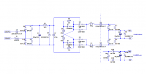
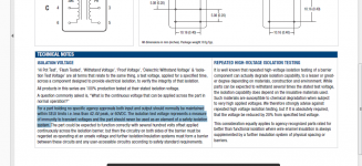
The power is first converted to a high frequency (~500kHz), and is then transmitted to the secondary via low-value Y-type capacitors.
These capacitors are specifically intended for mains to human-accessible parts connection, and are designed to be safe even under adverse conditions.
Nowadays, the main use for this type of cap is in helping to pass the EMC tests for switching supplies, but decades ago, they were also used to connect the earth or aerial of radio or TV receivers to the outside world (most of these receivers had a live chassis).
Here, the capacitance used is 2x 470pF, meaning the worst case leakage current is <70µA.
Below ~100µA, most people cannot notice a leakage current.
The circuit is symmetrical, to keep the common-mode interferences to a minimal level: the two arms are driven in antiphase, and since their impedance is identical, the HF drive cancels at the junction point.
In order to ensure a perfectly symmetrical drive (necessary for a good cancellation), the oscillator is a symmetrical multivibrator, to minimize any possible timing skew.
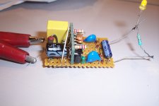
It is of course very important to use proper components and building techniques to guarantee the safety: the dropping cap of the capacitive supply must be an X-rated type, and the isolating capacitors must be Y-compliant.
In addition, it is necessary to respect proper clearances between the primary and secondary sides.
Also note that if the circuit is built without particular precaution (unselected components), there will be a non-negligible level of residual interference, mainly in the MW band, which should not matter too much these days.
If a better cleanliness is required, it is necessary to match the components in the two arms: capacitors and inductors. A small additional Y cap can also be added between the 0V points of the primary and the secondary.
The role of the inductors is three-fold: they provide some degree of conventional CM isolation, they reduce the effect of residual timing mismatches, and they partly compensate for the capacitive reactance of the coupling caps, thus improving the power transfer.
No attempt has been made to reach an exact cancellation, because any resonance would have a severely negative impact.
*The industry has explored other techniques, like ultrasonic or photovoltaic couplers, but they have remained anecdotal
Attachments
I have no knowledge of such a principle being presently in use, but I don't think the certification would pose any problem: millions of consumers are already exposed to the leakage current of such Y capacitors, very often larger than 470pF (in practically all class II SMPS adapters), and there has never been any objection to it (except perhaps from electrosensitive people, but there we venture into a not-so-technical field)Interesting design.
Would such a design be (is?) safety approved in the EU to be used for instance as a low power adapter?
Yes, that's the main criterion"Y-compliance", does that exclude short-circuit as a failure mechanism in safety analysis?
Many small pulse transformers, for gate drive, Ethernet, POE, etc and many small isolated DC-DC converters are Hi-pot tested to 1500V or 2500V, but that's not synonymous with safety isolation, like the Y certification: I would never rely on such a (purely functional) isolation for my safety or that of other human beings.why not use a small pulse isolation transformer, that are used for thyristor gate drive ?
for example murata 1017C ..
The advantage of Y capacitors is that they incorporate that safety level in a single, cheap and off-the-shelf component.
Note that I have already given (safe) alternative methods of providing low voltage isolated supplies, but this one does have some interesting advantages for a number of applications.
A simple, cheap, safe and reliable alternative source for low-power HV shunt supplies
Simplistic Colpitts oscillators used as low-tech converters
the murata is 4kV rms .. and has only 20pf of interwinding capacitance..
Sorry to insist, but Murata themselves make the distinction clear in their datasheet https://www.murata-ps.com/data/magnetics/kmp_1000.pdf
Functional and safety isolation are two different things and ignoring the distinction is at your peril.
60V is the absolute maximum voltage Murata allows for that kind of operation
Attachments
yes, you are right, the murata is not intended for mains isolation, most likely as the windings are bifilarly wound.
there should be others available that fulfill the requirements.
for example a toroid wound with furukawa TEX-E wire could do the job.
the 3C20 gapped toroids from ferroxcube (normally intended for classD filtering) are a good candidate.
there should be others available that fulfill the requirements.
for example a toroid wound with furukawa TEX-E wire could do the job.
the 3C20 gapped toroids from ferroxcube (normally intended for classD filtering) are a good candidate.
Yes, you can go back to the traditional solution of a small flyback: many magnetics manufacturers like Wurth offer small, certified transformers for that purpose, but you are left with the same problem, ie. needing to build a supply theoretically good for ~5W at least, when you are going to use 50mW, plus the need to handle the ~600V transitions generated by the FB, plus all the attendant circuitry.
Doable, for sure, but not extremely attractive to the DIYer.
This solution does require one chip, but is intrinsically short-proof (not something any switching supply hastily cobbled together can boast), and has an inherently limited level of interference.
Plus, the whole circuit is probably cheaper than a certified transformer alone, because all the components are dirt-cheap commodities (even critical components, like the Y and X caps).
Anyway, if you want to follow the small FB route, buying a small module from China or elsewhere is probably going to cost less and be less of a headache than assembling it all by yourself.
there are many tiny ac/dc switching supplies which deliver decent power and are have footprint of DIP 24 socket. This idea is for sure great, but can you fit it into DIP 24 footprint, while maintaining all safety distances as required? BTW, I hate Y capacitors and cut them out from all power supplies (Also I remove input filter middle point connection to output Vss), because when they are in, I can still fill stinging from connected device.
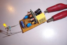
Using old TTH components on a naked PCB (or PCB-like support) like I did, most likely not.there are many tiny ac/dc switching supplies which deliver decent power and are have footprint of DIP 24 socket. This idea is for sure great, but can you fit it into DIP 24 footprint, while maintaining all safety distances as required?
With more modern components (SMD) or a suitable encapsulation, it would be rather easy.
BTW, your DIP24 modules almost certainly have them, otherwise they would have difficulties passing certification tests. They are probabbly commensurately small, like 100pF or 220pF, or even less.BTW, I hate Y capacitors and cut them out from all power supplies (Also I remove input filter middle point connection to output Vss), because when they are in, I can still fill stinging from connected device.
More fundamentally, I did mention the small, ready-made modules, but their power range is typically larger than for this type of supply: generally between 1 and 3W (perhaps a few hundreds mW for some).
This supply may not be particularly attractive, but its power range can be much lower.
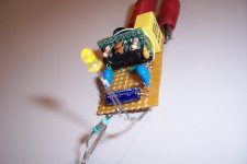
Nowadays, 5V/5mA is plenty enough for a microcontroller, a few LEDs and interfaces.
That represents 25mW of useful power. Because the circuit is inefficient, it will tap ~50mW from the mains, and it will do so permanently, because it is a shunt regulator. A waste?
Probably not: just to wake up a power supply module will already require more than that.
In addition, there is the robustness aspect to consider: this supply will normally survive surges two or three times the nominal voltage for seconds or more, not something any small FB can match.
I find it an inspiring idea suggesting a different approach to low power supply. The safety aspect is crucial and it seems Elvee has fully accounted for that.
There are, as also identified, alternatives that are technically different and often less elegant. Many can supply a higher power that may, however, be of no use.
Factors that are central in commercial electronics today are cost and low risk. When I see how little a 5W-25W power adapter can be bought for today, Elvee's circuit can hardly be sold cheaper. So, although I appreciate the possible novelty and functional elegance, I guess a competition on price will be fierce.
Good thinking, Elvee.
Last edited:
- Status
- This old topic is closed. If you want to reopen this topic, contact a moderator using the "Report Post" button.
- Home
- Amplifiers
- Power Supplies
- Y-isolated supplies