I'm looking for some practical instructions for measuring output impedance of a variable voltage PSU.
Mainly, I am interested to presentation a diagram graph of output impedance vs frequency, at different current levels on specific voltage output.
I have found some instructions on how to take advantage with an OPAMP for example, where the PSU fed the Vcc pin of opamp, while a signal generator apply a variable frequency signal at the input of opamp.
The problems at this solution are two:
- first, you can't to change the current of PSU and
- second, there is a problem with the low voltage range of 1.8-5Vdc with the opamp.
Signal generator, oscilloscope, electronic dc load are available.
To measure AC output impedance you need a load which works at AC. This basically means a resistor in series with a capacitor. Then there are basically two methods:
1. Measure some AC signal coming out of the PSU, while varying the AC load.
2. Use an amplifier to send an AC signal into the PSU output, via a resistor and capacitor. Vary the resistor and see how the AC voltage at the PSU output varies.
In either case, plot a graph or use Ohm's Law.
1. Measure some AC signal coming out of the PSU, while varying the AC load.
2. Use an amplifier to send an AC signal into the PSU output, via a resistor and capacitor. Vary the resistor and see how the AC voltage at the PSU output varies.
In either case, plot a graph or use Ohm's Law.
DF96, are you suggest to me something like posts 5 & 9 on this thread?
Measuring Output Impedance of Power Supply
Measuring Output Impedance of Power Supply
Thanks for the interesting on my question.
I have in mind to make a plot like this:
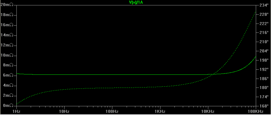
At the given current and voltage of the dc power supply, plot the relation of frequency and output impedance mainly.
Now, if I can to measure and the phase will be welcome!
On the post 5 & 9 of the link above, I can't understand how this implemented.
If I set my PSU on electronic dc load to a given current and voltage I could to measure the static impedance from the AC ripple or from the formula Zo=(Vno_load-Vload)/I, but this will be at the 50/60Hz of AC network.
Is that a diagram to understand how to setup a signal generator to this measurement?
I have in mind to make a plot like this:
At the given current and voltage of the dc power supply, plot the relation of frequency and output impedance mainly.
Now, if I can to measure and the phase will be welcome!
On the post 5 & 9 of the link above, I can't understand how this implemented.
If I set my PSU on electronic dc load to a given current and voltage I could to measure the static impedance from the AC ripple or from the formula Zo=(Vno_load-Vload)/I, but this will be at the 50/60Hz of AC network.
Is that a diagram to understand how to setup a signal generator to this measurement?
Actually you can do it with just a DC load. Just be sure that the peak value of the ac test current you inject into the supply output remains below the DC load current. To remain in the linear range use max 10% of the DC load current as peak ac current value.
You can inject the test current through a resistor like 100 ohms from a generator. Since the ac voltage at the supply output will be small enough to disregard, take the generator output voltage / 100 ohms as test current. For example, with 1V from the generator, the test current is 10mA rms.
Then do a freq sweep with the generator and measure the ac voltage at the supply output. Your output impedance is thus ac voltage/10mA, which of course is ac voltage * 100. Example: if you measure an ac voltage at the supply output of 1mV, the Zout at that freq is 100mohms. Easy ;-)
Jan
Last edited:
Thanks for the participation to this thread.
I have open the same almost question on the GB for Virtins MI Pro for RTX6001 autoranging/autoscaling & for soundcard end users. At this thread the same question include the hw & sw combination for a robotic measurement of psu impedance.
From this thread, a member give us some directions and a diagram that it is very useful with a general equipment. It likes very well as member Jan described above.
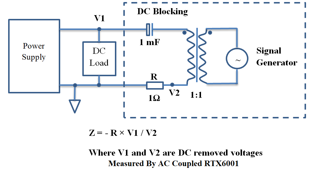
According to this diagram, we need a dc-load, a signal generator with a line transformer and a capacitor and resistor for the test.
I have open the same almost question on the GB for Virtins MI Pro for RTX6001 autoranging/autoscaling & for soundcard end users. At this thread the same question include the hw & sw combination for a robotic measurement of psu impedance.
From this thread, a member give us some directions and a diagram that it is very useful with a general equipment. It likes very well as member Jan described above.
According to this diagram, we need a dc-load, a signal generator with a line transformer and a capacitor and resistor for the test.
If using a DC load you might first have to measure the AC impedance of the DC load. Otherwise what you are measuring is the parallel combination of AC impedances of DC load and PSU.
DF, correct, yes. Two comments:
- I don't know of any DC load that has an AC impedance that is significant relative to the sub-milliohm output impedance of a regulator;
- You NEED a DC load because you want to measure the supply under actual working conditions.
Question: Do you consider the output bypass capacitor part of the regulator or part of the load? Strictly speaking, you should disconnect it when measuring regulator Zout, but that can make it oscillate.
Again, a good regulator should have Zout appreciably lower that the ESR of the bypass cap, so I would leave it in anyway.
You did remember that for a stable regulator you use an output bypass cap with at least 1 ohm ESR, right ;-)
Jan
Thanks for the participation to this thread.
I have open the same almost question on the GB for Virtins MI Pro for RTX6001 autoranging/autoscaling & for soundcard end users. At this thread the same question include the hw & sw combination for a robotic measurement of psu impedance.
From this thread, a member give us some directions and a diagram that it is very useful with a general equipment. It likes very well as member Jan described above.
According to this diagram, we need a dc-load, a signal generator with a line transformer and a capacitor and resistor for the test.
No idea why you would need the xformer, except to lower the noise level for the RTX.
Jan
Jan, the same questions I have done to the initial thread that this diagram uploaded.
Perhaps, because at the points V1, V2 must joined an Analyzer that communicates with a PC, the transformer "breaks" ground loop problems!
For this thread, that we are talking now, I think that the same diagram without transformer will be OK.
Perhaps, because at the points V1, V2 must joined an Analyzer that communicates with a PC, the transformer "breaks" ground loop problems!
For this thread, that we are talking now, I think that the same diagram without transformer will be OK.
Yes that could be the reason. Although I never had problems with that. What is important is to connect the test current input very close to the regulation point, preferably where the regulator feedback is taken off. There the impedance is lowest. Of course, you only get that benefit if you later also connect the load to that same point.
The ground or return lead of the test equipment/oscillator also needs to be connected to some sort of central point of the regulator. My regulators always have a 'reference' ground point where the gnd of the reference and the feedback network are connected and that is where the test gnd (and later the load) should be connected.
Believe me, measuring anything below a few 10's of milliohms is VERY difficult! Hint: if the curve of output impedance over frequency is flat, you are not measuring 'deep' enough.
Jan
You are the first to mention a regulator, but I guess I should have assumed that from the description 'variable voltage supply'. I agree that a DC load may be needed.jan.didden said:DF, correct, yes. Two comments:
- I don't know of any DC load that has an AC impedance that is significant relative to the sub-milliohm output impedance of a regulator;
- You NEED a DC load because you want to measure the supply under actual working conditions.
Question: Do you consider the output bypass capacitor part of the regulator or part of the load? Strictly speaking, you should disconnect it when measuring regulator Zout, but that can make it oscillate.
Again, a good regulator should have Zout appreciably lower that the ESR of the bypass cap, so I would leave it in anyway.
You did remember that for a stable regulator you use an output bypass cap with at least 1 ohm ESR, right ;-)
I take any capacitor in the PSU to be part of the PSU. It may raise or lower output impedance, depending on how inductive the regulator output is.
- Status
- This old topic is closed. If you want to reopen this topic, contact a moderator using the "Report Post" button.
- Home
- Amplifiers
- Power Supplies
- Practical instructions for PSU output impedance measuring vs frequency