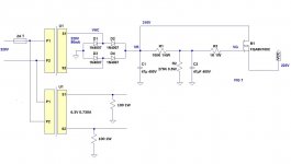
Hi, I'm using a capacitance multiplier circuit after s.s rectification in a tube amplifier. I wondered if a particular mosfet can somehow change the overall sound, I swapped from 2SK1603 to a more powerful IRFP450 but I have an impression that the previous was better (more neat and detailed), so I'm a little bit confused
If the voltage is the same, there will be no difference in sound quality. If the voltage is less or more the distortion point will change. If the FET has enough gain then the voltage will stay near the same when drawing current. If the gain is less the voltage may sag under load conditions. Measure the voltages and compare.
Hi, I'm using a capacitance multiplier circuit after s.s rectification in a tube amplifier. I wondered if a particular mosfet can somehow change the overall sound, I swapped from 2SK1603 to a more powerful IRFP450 but I have an impression that the previous was better (more neat and detailed), so I'm a little bit confused
In general, it's never a good idea to swap components without understanding how the modified circuit will behave. The classic case is "op-amp rolling", when a "tweaker" swaps op-amps that have vastly different electrical characteristics and then associates the "sound" of the modified circuit behavior solely with the "sound" of the op-amp. When a particular op-amp is inserted into a circuit that is not optimized for it, it may perform very poorly. Yet you can find these "tweak and listen" approaches all over the web.
So, I am wondering if the same kind of thing might be happening here... possibly not, but you didn't provide much in the way of details.
How did you check whether the cap multiplier circuit is still working properly?
How do you know that the IRFP450 will function properly (or as desired) in the circuit?
Please provide more information about what you did and how you judged the "sound" and performance of the modified circuit?
Last edited:
If the voltage is the same, there will be no difference in sound quality. If the voltage is less or more the distortion point will change. If the FET has enough gain then the voltage will stay near the same when drawing current. If the gain is less the voltage may sag under load conditions. Measure the voltages and compare.
In effect the 2SK1603 voltage is 8-10 volt higher than IRFP450
In general, it's never a good idea to swap components without understanding how the modified circuit will behave. The classic case is "op-amp rolling", when a "tweaker" swaps op-amps that have vastly different electrical characteristics and then associates the "sound" of the modified circuit behavior solely with the "sound" of the op-amp. When a particular op-amp is inserted into a circuit that is not optimized for it, it may perform very poorly. Yet you can find these "tweak and listen" approaches all over the web.
So, I am wondering if the same kind of thing might be happening here... possibly not, but you didn't provide much in the way of details.
How did you check whether the cap multiplier circuit is still working properly?
How do you know that the IRFP450 will function properly (or as desired) in the circuit?
Please provide more information about what you did and how you judged the "sound" and performance of the modified circuit?
Well, about IRFP450 I'm not sure that things go well...first of all, when operating Vgs < Vth so it's nor in linear nor saturation zone. I want the mosfet working properly, I deduce that its specs are not suitable with my circuit. Moreover, the IRFP450 is rated 500V for Vds and it's advisable to be > 2 times the rectified voltage of the PSU (mine is 370v no load) .
Different thing with 2SK1603, Vgs is 3.2V so greater than 2V of threshold and it keeps fairly constant. Also voltage regulation seems good.
The 'cap multiplier' is actually just a source follower fed from a first order low pass filter. As such it will be subject to all the usual source follower characteristics. Output impedance will depend on the device, HF stability will depend on the device and the load capacitance etc.
Why on earth did you change from a decent FET to a monster?
I don't understand why indaco says you get 8-10V more with the old, there's not that much difference in Vgs in the two, and the IRFP has higher trasnconductance so the they should give about the same output voltage.
The IRFP should have better performance at low frequency (due to higher Gm) but poorer performance at higher frequencies (due to higher parasitic capacitances). But if that is audible I dunno...
Why on earth did you change from a decent FET to a monster?
I don't understand why indaco says you get 8-10V more with the old, there's not that much difference in Vgs in the two, and the IRFP has higher trasnconductance so the they should give about the same output voltage.
The IRFP should have better performance at low frequency (due to higher Gm) but poorer performance at higher frequencies (due to higher parasitic capacitances). But if that is audible I dunno...
The main reason was to improve the heat dissipation, using a bigger heatsink, but I didn't take into account the consideration sonically.
The main reason was to improve the heat dissipation, using a bigger heatsink, but I didn't take into account the consideration sonically.
I see your point, logical enough. Interesting you can hear the difference...wow this search for ideal amplifier with ideal power supply with ideal cables with ideal sources with ideal music all terminating into ideal speakers just keeps us all so busy!
I see your point, logical enough. Interesting you can hear the difference...wow this search for ideal amplifier with ideal power supply with ideal cables with ideal sources with ideal music all terminating into ideal speakers just keeps us all so busy!
In reality, I know the importance of the PSU especially with tubes...I try to be practical and for reason of space too I don't want to use complicated circuits. Oftentimes the first solution we think is the best
")
- Status
- This old topic is closed. If you want to reopen this topic, contact a moderator using the "Report Post" button.
- Home
- Amplifiers
- Power Supplies
- The "sound" of a mosfet in capacitance multiplier