I suspect you are on the right track. I have no experience with this power supply, but I stumbled on a trick that might help. I place a ferrite bead on the ground line entering each of my components. Not on the entire power cable as I find this has a small negative impact on sound. But placed on the safety wire, it improved sound as if a noise floor lowered. I'd guess that its dampening the RF noise running through the ground.I suspect what you are hearing here are second order effects to do with the grounding scheme of your system. Everyone knows noughts and ones are just that. Bit perfect is easy right?... but there is so much more going on than that. I find it helpful not to think of system elements as discreet boxes that have no relationships to one another. They are all interconnected and interacting both through interconnects and also your AC power supply. My hunch is your digital sources are likely to be producing a lot of high frequency radio spectrum noise. This does not behave like DC. It can crawl everywhere through power supply and interconnects. How do you solve this? I'd look upgrading your digital source to something that is optimised for audio. The ones and noughts will be the same but all the second order effects, like RF crawling through the power supply, should be much better.
Attachments
Can UcConditioner 5V be used for Lithium-titanate battery? The output voltage of LTO battery is relatively stable and the internal resistance is also very low. LTO also has the characteristics of fast charging, so LTO has better electrical properties than supercapacitors.
LTO is safer than LiFePO4, and is more suitable for use in audio applications that do not require high energy density.

LTO is safer than LiFePO4, and is more suitable for use in audio applications that do not require high energy density.
Last edited:
Hello,
i tried to find the answer but i couldn't.
If I want two ultracaps directly to a LifePo4 cell
(like Ian does here: https://live.staticflickr.com/65535/49076318092_eb8a3c8244_o.jpg)
but without ian boards, where should i put a BMS for the battery? Is it OK if I put it after the cell and capacitors since the capacitors follow the voltage of the cell?
This is a long thread and my question might have been answered already.
I am planing for a PSU and my question is if I should or need to use a choke together with UcConditioner or if the conditioner can take the place of the choke ?
(The PSU is for a dac and FiFopi streamer)
I am planing for a PSU and my question is if I should or need to use a choke together with UcConditioner or if the conditioner can take the place of the choke ?
(The PSU is for a dac and FiFopi streamer)
")
I'm completely new to the DIY game and haven't worked on my project for a few months, but I'll give it a shot.
I don't think a choke is necessary. That choke in Ian's photo was before UcConditioner was released. That was the old school way or if you need a more advanced SuperCap solution such as 12V, etc.
Batteries are 3.3V multiples and SuperCaps are 2.5V multiples.
So if you have a Chord Qutest DAC or RPi which is 5V. What you can do is MKIII 6.6V (2x3.3V) -> Ian's LPS -> UcConditioner 5V (2x2.5V). That's what I'm planning this summer and what Ian suggested if I want 5V pure battery.
For the MKIII + UcHybrid, 2 (2X2.5V) SuperCaps not ONE are needed for 3.3V. So the 5V SuperCap total is scaled back down to 3.3V. I don't think a choke is involved to scale down and that it's handled within the UcHybrid logic internally.
Please take with pinch of salt. Just trying to give a general idea than nitty gritty details. So I believe it's UcConditioner takes place of the choke. Please double-check before proceeding.
I need to read the manuals again to refresh my memory. If you are not using 5V or 3.3V, then you may need a choke as those are the only UcConditioner options for now. Crossing fingers on a UcConditioner 12V end of the year.
Last edited:
A choke is not the same as a capacitor.
A choke generates voltage and is connected in series in the power line. A capacitor is a current tank and is connected parallel to the power line.
For digital a power supply with ultracapacitors is a good match due to the hf current demand that needs a low esr.
A choke generates voltage and is connected in series in the power line. A capacitor is a current tank and is connected parallel to the power line.
For digital a power supply with ultracapacitors is a good match due to the hf current demand that needs a low esr.
Hello,
A power supply using transformer and a rectifier will always come with something disturbing that cannot be dealt with 100% by a cap and/or some active circuit.
In most situations ( i think all) the right choke will improve things.
ALL batteries seem to make noise and it looks like the latest supercaps are good at reducing it.
Greetings,Eduard
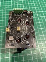
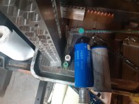
UcConditioner New 450F BCAP0450 P270 S18 mounting solution
I understand that the ultra-capacitors are now having very long lead time under this COVID situation.
But just found the new MAXWELL 450F BCAP0450 P270 S18 ultra-capacitors are still keep in stock. This ultra-capacitor will be great to work with my UcConditioner. But the footprint is different.
Now I have solution to mount them to my UcConditioner.
1. Bent the two NC pins and then cover with tape to avoid any possible short circuit.
2. Solder the two 450F UCs to the UcConditioner at the bottom side of the UcConditioner PCB.
3. Make sure + and - are at correct positions.
Please refer the attached pictures for details. Please let me know if you have any questions.
If it is required, you can disassemble the input/output terminal block connectors and then flip/solder them to the other side of PCB.
Good weekend.
Ian
Attachments
Last edited:
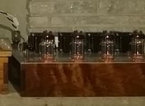
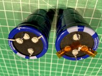
Nice to see alternative power schemes! I'm almost a year into a full system battery powered project. I was using the 2170 lipo, but lately I'm working very hard to get a LTO system developed. Here's to stored energy 
Attachments
Hello,
I just ordered parts in Canada.
Because i need to order chokes anyway i decided to make an LCRC supply followed by an LM338 . Will use one for the LIfepo4 and one for a Roon nucleus.
The 350 mH 4A input choke will get rid of a lot of garbage coming out of the wall, the switching from the rectifier ( because there will be no switching) and the charging pulses.
With the Roon it will probably work both ways because it is full of switching supplies.
Psud will show a gentle rise of the voltage and a ripple close to 1 mV.
Some experts say that the amount of ripple isnt that important because of the regulator. It is more about things the choke can do and the regulator cannot.
Maybe in the lifepo4 it will be mainly the 5 volt supply that will profit because they lifepo4 could be disconnected from the charging circuit once they are '' full ''
The manual is not clear and Ian not answered . Can i create 3,3 volt each with two or more in parallel to give them a bigger energy level???
Greetings, Eduard
Hello Ian,
I tried it with PSUD
Using 350 millihenry 4A 2,8 ohm ( but i had to add an extra resistor to get no overshoot)
Then 94000 microfarad 200 milliohm
10 mOhm resistor
47000 microfarad 400 milliohm with a 3,5A current load.
No PSUD on this PC but if i am right this were the values to create a 21 volt input for the LM338.
Maybe you have a more sophisticated program?
Greetings, Eduard
Hi, everyone,
My name is Igor and I desperately need some help.
I bought Lifepo4 and 10 batteries of which I decided to use only 7.
My idea was to have 3.3V on J1, 3.3V on J2, 3.3V on J4 (by shorting TP11-12) and 13.2V on J3.
I have batteries in BT1,2,3,4,5,6,7 and no batteries in 8,9 and 10.
When I connect the rails to Ian's DAC (3 x 3.3V) and I/V STD Mk II (13.2V) music starts playing for 3 seconds and then in 3-5 seconds no music at all.
On the other hand, if the I/V is LL1544A, everything works perfectly (no 13.2V needed).
What did I do wrong?
All the very best with your projects,
Igor
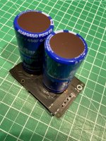
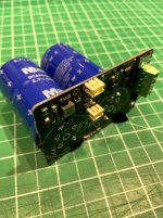
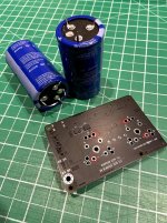
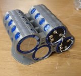
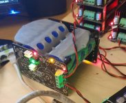
My version is for a more compact placement in the case.
A trial version, the racks are 2.5 mm after the epoxy glued.
I can share a 3D model.
A trial version, the racks are 2.5 mm after the epoxy glued.
I can share a 3D model.
Attachments
Last edited:
Hi, everyone,
My name is Igor and I desperately need some help.
I bought Lifepo4 and 10 batteries of which I decided to use only 7.
My idea was to have 3.3V on J1, 3.3V on J2, 3.3V on J4 (by shorting TP11-12) and 13.2V on J3.
I have batteries in BT1,2,3,4,5,6,7 and no batteries in 8,9 and 10.
When I connect the rails to Ian's DAC (3 x 3.3V) and I/V STD Mk II (13.2V) music starts playing for 3 seconds and then in 3-5 seconds no music at all.
On the other hand, if the I/V is LL1544A, everything works perfectly (no 13.2V needed).
What did I do wrong?
All the very best with your projects,
Igor
If you use the standard iv board with the opamps you need to feed it with +13v and -13v so you need all batteries connected.
- Home
- Amplifiers
- Power Supplies
- Develop ultra capacitor power supply and LiFePO4 battery power supply