(+)BT2 to (-)BT2 - 3,25vStart systematically measuring from (+)BT2 to the (-) of the other batteries to determine where the problem is.
(+)BT2 to (-)BT10 - drops from around 3,2V to 0
(+)BT2 to (-)BT9 - drops from around -0,2V to 0
(+)BT2 to (-)BT8 - drops from around -3,2 to 0
Exactly the same situation when measuring from (+)BT5 to (-)BT4/3/1
While doing the measurement and letting (+)BT2 to (-)BT10 drop down to 0 (in about minute or more) the next ones measure differently:
(+)BT2 to (-)BT9 - starts dropping from -3,xV to 0
(+)BT2 to (-)BT8 - drops from around -6,x to 0
Same thing on the other side, starting from (+)BT5 to (-)BT4
I can't make any conclusions from that, what about you guys?
Just to be sure I re-soldered the battery holders. Pushed the holder terminal (metal part) down while soldering. I hope this is the right way to do it.If (+)BT10 to (-)BT8 =9.9V then the issue is with BT2. Look closely at the battery terminals and remove any plastic in the center.
To be honest, I don't exactly understand the "barely elevated plastic in the center of the negative terminal causing discontinuity".
Here is what I discovered:
When measuring voltage from holder terminals, not touching the batteries but only holder terminal, all give correct reading of 3,25V (when unit is ON!).
But when pushing down and forcing the holder terminal against the battery, the power supply does similar clicking sound, like when turning on. This happens with multiple battery holders, but not all.
Also I'm able to create the same clicking noise while gently pushing the battery holder sides (+ & -) with fingers, pressing the terminals against battery.
So does that mean, that there is problem with battery connection to the holder terminals? Not sure how I can fix this. Tried to bend holder terminal to provide more force but this did not resolve the issue.
The plastic cover of the battery sticks out at the bottom so the metal plate effectively sinks lower and the battery holder terminal might not be making contact. It seems that has been a problem for few people and might explain the clicking sounds when you are pressing on the holders.
Just to be sure I re-soldered the battery holders. Pushed the holder terminal (metal part) down while soldering. I hope this is the right way to do it.
To be honest, I don't exactly understand the "barely elevated plastic in the center of the negative terminal causing discontinuity".
Here is what I discovered:
When measuring voltage from holder terminals, not touching the batteries but only holder terminal, all give correct reading of 3,25V (when unit is ON!).
But when pushing down and forcing the holder terminal against the battery, the power supply does similar clicking sound, like when turning on. This happens with multiple battery holders, but not all.
Also I'm able to create the same clicking noise while gently pushing the battery holder sides (+ & -) with fingers, pressing the terminals against battery.
So does that mean, that there is problem with battery connection to the holder terminals? Not sure how I can fix this. Tried to bend holder terminal to provide more force but this did not resolve the issue.
Good move resoldering, that would have been my next suggestion. As for the connection issue see this post
Develop ultra capacitor power supply and LiFePO4 battery power supply
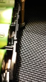
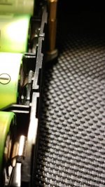
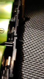
Visually all the connections look good, made some photos.
If the connection would be bad, then measuring from the terminal (when unit is ON) should give 0, but not 3,25V. All of the readings are OK.
If the connection would be bad, then measuring from the terminal (when unit is ON) should give 0, but not 3,25V. All of the readings are OK.
Attachments
Good move resoldering, that would have been my next suggestion. As for the connection issue see this post
Develop ultra capacitor power supply and LiFePO4 battery power supply
I experienced this before and was caused by cold soldering of relay. Re-solder all relays and see if it solve your problem.
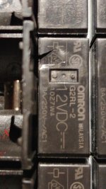
Thanks for the suggestion. Did that, but no change. One of the relays seems to be damaged. I didn't notice it before, so not sure, how long it's been like that. Added a photo.Re-solder all relays and see if it solve your problem.
I should probably change it? Any hints, how to get it removed. It' has 8 connection points
")
Attachments
Having tried to do that, I found it is nearly impossible without damaging the board. I had used solder wick to remove all of the solder from the board bottom side of the relay pins and pins on the top side were still soldered to the pads there. I could repair the board, but don't recommend this.
Ian may have a better suggestion. Me, I'd go buy 2-3 of those relays, then use a pair of pliers to crush one apart from the top to see how they break. Then I'd VERY CAREFULLY do that with the damaged one on the board to get down to where I could unsolder and remove each pin seperately.
Wait until you hear from Ian before attempting this! Again, he might have a better idea!
Greg in Mississippi
Thanks for the suggestion. Did that, but no change. One of the relays seems to be damaged. I didn't notice it before, so not sure, how long it's been like that. Added a photo.
I should probably change it? Any hints, how to get it removed. It' has 8 connection points
Hi nielsek,
What happened to it? Poor relay
The PCB of LifePO4 board is very special. It has double thickness copper layers (For high current application).
What Greg said is correct, it's really hard to replace it. You will need a Vacuum desoldering gun. Can you access that tool?
Regards,
Ian
This is the board where I accidentally put one battery in wrong polarity and blew a resistor (Post 642). Once I changed it, I got the the board working/charging. I only used the first two rails. Now when wanted to use the other ones, found out they are not working.What happened to it? Poor relay
About the broken relay, I have no idea how it got physically damaged. Maybe, when I resoldered all the holders.
I have a simple vacuum desoldering device, but with that one it's hard to succeed.
Is it possible to check the relays? Both of the rails (J3 and J4) act the same.
This is the board where I accidentally put one battery in wrong polarity and blew a resistor (Post 642). Once I changed it, I got the the board working/charging. I only used the first two rails. Now when wanted to use the other ones, found out they are not working.
About the broken relay, I have no idea how it got physically damaged. Maybe, when I resoldered all the holders.
I have a simple vacuum desoldering device, but with that one it's hard to succeed.
Is it possible to check the relays? Both of the rails (J3 and J4) act the same.
@Nielsek,
Sorry about the issue.
You can find the datasheet from the P/N of the relays. So you may check the connections in both ON and OFF states.
Don't try to remove the relay if you don't have suitable tools.
Regards,
Ian
I've found that components like the relay that are super difficult to get out in one go are best removed by very carefully completely destroying the case with something like a dremel. Reduce it to just the contacts with a cutter. That way you minimise the heating and can tackle one through hole at a time.
I found that the battery-powered modules can be improved. I found a phenomenon what it is not good that the current output from the battery is directly input into the load as long as the power consumption of the load is more than 200mA. Compared with the LDO module, the sound quality of the battery-powered moduleds will be worse for over 200mA load, but for the power consumption below 200mA load, such as the clock board, sound quality can be improved power by the battery. I think this is mainly because the load has relatively large in power consumption, the battery power will be significantly faster reduced, the current output from the battery will generate a large equivalent current ripple. However, using parallel to increase the battery capacity, although the equivalent current ripple can be reduced, but parallel battery will have other problems. According to my experience, the best way is to still supply power from the parallel battery, but use a parallel connection such as LT3045 to provide enough current to power the DAC, and also try to add high-quality capacitors to the output circuit. In short, I sincerely hope that IAN can actually try to follow my experience, and then propose a better solution for everyone
Last edited:
LifePO4?
It is the same for each battery power supply.
Mah. Not all the batteries have the same response.It is the same for each battery power supply.
It is the same for each battery power supply.
No it's not. Impedance is different for different chemicals. Also transient response...
Strange that I dont have any issues at 200mA. At 1A there are also no problems. Do you have any measurements or how can i check this by myself ?
Hoping someone can help as I'm having an issue with my LifePo4 board.
I haven't used the Lifepo4 board for a while and just set it up again with batteries only on BT2, 7, and 5,6 (bottom 4 slots - 2 batteries on each side nearest the outputs) so I can have 2x 3.3v out on J3 & J4 to run an SD card player and HDMI module. I have shorted TP 11-12, TP5-6 as instructions, which are the next empty slots to the batteries.
Board works fine and music plays okay but after 10 seconds it shuts off. I've checked all the batteries (each one is around 3.34v) and the soldering, all looks fine. Any suggestions greatly appreciated on what might be the issue?
Last edited:
- Home
- Amplifiers
- Power Supplies
- Develop ultra capacitor power supply and LiFePO4 battery power supply