So I obtained the LiFePO4 specifically as a replacement for the NiMH battery pack I made for EUVL’s SEN IV. This circuit works best with a floating supply.
Zen -> Cen -> Sen, evolution of a minimalistic IV Converter
Upon first hookup the results were disappointing. There was a lot of hum/hiss audible from my 8’ listening distance, a rather violent on/off pop (even lightly tapping the encoder knob produced a zap through the speakers) and, something I haven’t experienced in a while, listening fatigue.
Floating supplies are very sensitive to emf pickup so I started wrapping the batteries with Al & Cu foil. Some improvement. Encouraged, I kept adding shielding (magnet shield on the top Magnetic Shielding Materials). I now had to go to 2’ to hear the noise. Finally, earth-grounding things just about slayed the noise (tiny bit detectable with ear to driver). It also stopped the pops from merely tapping the board but not the on/off one (still working on solution to that).
Okay, so why am I telling you this? The improvement in the music was much more than a mere lowering of the noise floor. There was more texture to the notes, better atmosphere, improved bass, less sibilance on "s", and no more listening fatigue. This has made me reconsider the importance of shielding and perhaps explain improvements like this reported my Markw4
IanCanada's Latest RPi GB Goodies Impressions... and your tweaks, mods and hints...
Last edited:
@alazira
It's so great that you implemented the LifePO4 power supply to CES/SEN I/V stage. Congratulations!
I know that the LifePO4 power supply is ideal for floating power application. So that what I want to do the next. But I've never thought the noise issue. Thank you so much for sharing your experiences. Do you have pictures of your system?
Regards,
Ian
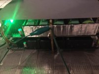
Magnet shield on top, giron mat bottom. I will see if I can find a similar weight aluminum sheet to compare with the magnet shield from less emf. An aluminum foil I tried was not nearly as effective. In this picture the earth ground is not connected to the magnet shield. Using the thin clip wire to attach it to ground improved things but grounding directly much more so.
I tried a larger/heavier aluminum piece (from F5-X amp). It works as good as the magnet shield, but it is much more substantial so I don't know if Al is = to magnet shield or not, but shielding your LiFePO4 in an grounded aluminum case is probably a good idea.
I've been troubleshooting my 3rd LiFePO4 board which has a loud hum an order of magnitude more than what the other boards started with.
Things I've tried:
Checked output voltages - correct
Shielding - minimal effect
Swap batteries with the other boards - no difference
inspect for missing resistors/capacitors - all present
Is there anything else I could try?
Attachments
Hi Supersurfer,
It is comming out of the speaker. I did have the smps issue, but after changing the smps to 15V (it was selectable) it is now quiet. It is just one board that is a problem. The other boards in the same setup are okay.
Ian, I've read the new manual. Is there something specific you were thinking? The only thing I can see to try is checking the R015 resistors.
All of the R015 check out. Anything else I can try? Might try to reflow some solder even though everything looks okay.
Hi Ian,
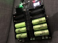
Ive assembled my battery board. J1 and J2 outputs 3.3v. however J3 and J4 has no output. Configured J3 and J4 to output 6.6v. BT2 and BT10 were assembled then shorted tp9 and tp10, assembled bt5 and bt4 then shorted tp3 and tp4 but no output. All other battery cells were not assembled.
Please help.
Thanks
Attachments
Last edited:
Having an issue with J2 output on Gen 2 board. The board goes into short protection shortly after starting. All outputs with the exception of J2 are at voltage spec. J2 measures 3.0V before it shuts off with protection. When circuit protection is turned off for J2 the output at J2 measures correctly at 3.3V. In fact I have used it for several hours with SCP2 disabled and it works well. I replaced the R015 resistor hoping that would remedy the issue but it has not.
Suggestions/thoughts??
Suggestions/thoughts??
Having an issue with J2 output on Gen 2 board. The board goes into short protection shortly after starting. All outputs with the exception of J2 are at voltage spec. J2 measures 3.0V before it shuts off with protection. When circuit protection is turned off for J2 the output at J2 measures correctly at 3.3V. In fact I have used it for several hours with SCP2 disabled and it works well. I replaced the R015 resistor hoping that would remedy the issue but it has not.
Suggestions/thoughts??
3.0V is lower than the protection triggering level. Why did you replace R015?
Regards,
Ian
Hi Ian
I assembled life p4 battery board , display is no lighting and j2 only 3.2 v the rest no power .
Best
I have a similar issue. Only the 3.3v outputs are working. All others had no output
Those issues are normally related to assemble:
1. The PCB copper are 2 oz (double thickness) to get higher current, so you will need higher power solder iron. Sometimes can get poor soldering points inside the PCB holes though they look good.
2. Some battery holders didn't contact to battery terminals very well.
3. There could be bad battery cells. To find them out you will need to measure the battery voltage either at "ON" state or before assemble them to PCB.
4. Different from other power supply, for safety reason there are lot of protection features. If there is anything wrong, those protection could be triggered and fuses can also be blown.
5. With battery cells installed, it will always be powered even you disconnect the DC input. So things underneath PCB can still cause short circuit, as well as tools such tweezers and screw drivers.
Please do read the user's manual with careful before you assemble the LifePO4 power supply.
Please no worry, I'm here to help.
Regards,
Ian
1. Will check all solder joints but J2 does provide 3.3V when short protection is disabled.
2. I am not using battery holders.
3. Will check battery voltages again but as noted previously I did check the voltages both off and on. They were all 3.33V.
4. The voltage issue at J2 when short protection is enabled exists without any connections to J2.
5. Will have a look to make sure there is not something causing a short on the underside of the board.
The puzzling thing is it was working until the poor solder joint on one of the battery tabs (BT7??) failed when I had the board out of the case. The issue appeared after that.
Hi Ian,
Is it safe to parallel j1 and j2 to get 6.6v output? Reason i asked is i need 3 6.6v outputs.
Thanks
Series? It is ok to do series. Parallel would double capacity but not voltage.
Hi there.
Let me ask you a question.
The thread title announces an ultracap supply. Why has this project turned into a battery supply project? Did I miss something?
I thought Ian even confirmed when we were having the discussions around the best-of-all-options some time back that a supercap supply would be No.1 choice !?!?
Thx.
- Home
- Amplifiers
- Power Supplies
- Develop ultra capacitor power supply and LiFePO4 battery power supply