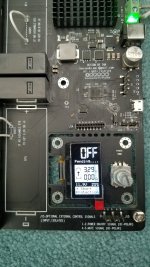
Photos of my MkII board...
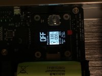
The first one shows the display right after it auto-shuts off, after it running 10 seconds. All batteries measure the same voltage before and after.
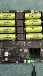
Just to try something, I will remove the jumpers and install the last 2 battery holders and batteries, since I just received the remainder of my order.
The first one shows the display right after it auto-shuts off, after it running 10 seconds. All batteries measure the same voltage before and after.
Just to try something, I will remove the jumpers and install the last 2 battery holders and batteries, since I just received the remainder of my order.
Attachments
@Heathkit. I had a problem with a bad cell (brand new!) which caused the board to show some similar behaviour. Check all the large 0.015 ohm current sense resistors on the bottom of the board close to the relays have not gone open circuit. If the cell is hogging tons of current they blow to protect the board and you get that warning before shut down. The bad battery voltage looked OK when initially measured paradoxically.
Problem solved!
Thank you Greg and Simon for your suggestions, it helped track down what was going on.
It didn't make sense because the batteries all measured fine with it OFF, but when running, 2 cells measured 0 vdc. So that immediately told me either a faulty battery or holder. I tried swapping positions of those two cells and the zero volts situation moved with the suspect cells, so now I'm wondering how 2 out of 10 brand new cells could be bad?
Further testing with the unit running showed when putting the test leads on the holder terminals there was 0 vdc, BUT when you moved the leads in a bit and contacted the battery itself, then it was reading 3.3 vdc. What the heck!
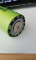
It turns out 2 of my batteries were not making contact on the negative terminal in the holder due to the plastic center being slightly raised above the negative contact surface. See photo attached. These 2 cells were carefully corrected with an xacto knife.
Thank you Greg and Simon for your suggestions, it helped track down what was going on.
It didn't make sense because the batteries all measured fine with it OFF, but when running, 2 cells measured 0 vdc. So that immediately told me either a faulty battery or holder. I tried swapping positions of those two cells and the zero volts situation moved with the suspect cells, so now I'm wondering how 2 out of 10 brand new cells could be bad?
Further testing with the unit running showed when putting the test leads on the holder terminals there was 0 vdc, BUT when you moved the leads in a bit and contacted the battery itself, then it was reading 3.3 vdc. What the heck!
It turns out 2 of my batteries were not making contact on the negative terminal in the holder due to the plastic center being slightly raised above the negative contact surface. See photo attached. These 2 cells were carefully corrected with an xacto knife.
Attachments
that means it's ready to go, Casshan.
Push the nob down for a couple of seconds to fire it up.
-Steve
Hi Steve, thanks a lot!
Which is the standard duration of the battery ?
I'm using the lifePO4 to power a raspberry 3B+ (with the 5Vouput) the fifoPi and the DAC Es30982qm (with the two 3.3 outputs) and the Standard I/V board with the other two output connected to have +13.2V 0 -13.2V
So I'm using all 10 batteries.
But after 90 min the LifePO start to recharge the batteries.
Is it normal?
May I have to wait some cycle charge discharge to have a longer period available?
D
Deleted member 537459
Auto off is at the default value (5h).AMaybe you need change auto off by timing? I assembled 4 lifepo 4 and all is pefect for 4-5 ours. 2 of them i mount another 2 batteries with relay for have 3 separate 3.3v for dac

So I suppose this is not the problem.
Interesting you expansion. Where did u attached ? In parallel to other two batteries? Which relay are u using ?
D
Deleted member 537459
@paoloilpizzo,
I can get 4-5 hours of runtime powering the FiFoPi with either Crysteks or NDK SDA, either if Ian's GB DAC boards, and the IVStd with 2 Sparkos discrete opamps (I'm using the balanced output.
Have you measured the cell voltages before power-on, while running, and after it shuts down? If not, can you do that and report back?
It sounds like they are either not well-charged (I haven't checked, but I suspect it takes a couple of hours of charging time to get them to full charge though they do charge at a fairly fast rate at first) OR they may be substandard cells. Remind us, where did you get them? Were they new or used?
Let us know.
Greg in Mississippi
AMaybe you need change auto off by timing? I assembled 4 lifepo 4 and all is pefect for 4-5 ours. 2 of them i mount another 2 batteries with relay for have 3 separate 3.3v for dac
Very cool. I too would like to see how you connected it.
Another thing I was thinking of was rewireing for "always on" where the relay would be for turning off charging, but I wasn't sure if the system needed the batteries isolated for proper charging.
@alazira,
AFAIK, you can't configure Ian's LiFePO4 supply to be always-on in the current configuration. in 'Off' mode, the cells are all charged separately, while in 'On' mode, up to 4 of them may be connected in series to give a higher voltage than 3.3V.
Those two modes are fundamentally incompatible.
The relays connect the cells either to the output side (with some in series) or charge side (with all connected to the charge circuits separately.
I DID float the idea at one time of using 2 LiFePO4 boards that had shared control and output connections... with new firmware, you could turn the stack on and one would provide the output while the other charged... then when the one provided the output reached the turn-off voltage, the boards would swap. That is possible, but not available yet and AFAIK, not planned.
Greg in Mississippi
AMaybe you need change auto off by timing? I assembled 4 lifepo 4 and all is pefect for 4-5 ours. 2 of them i mount another 2 batteries with relay for have 3 separate 3.3v for dac
Very cool. I too would like to see how you connected it.
+1.
Something I would also like to try supplying 3 x 3.3V to the DAC but the additional cost and size of another Life PO4 board is putting me off, are the gains of the triple supply worthwhile ?
Last edited:

- Home
- Amplifiers
- Power Supplies
- Develop ultra capacitor power supply and LiFePO4 battery power supply