@AudioKill,
This may be as much as anything a case of mis-matched expectations. AFAIK, Ian does the gear he GB's to share some of the designs he developed for his personal use with the DIY community. He is not, again AFAIK, planning to develop this into a business. He already has a successful and lucrative career as a medical device electronics designer/developer. Based on the prices he charges for the units, he's not in this to make money. Once you count his time and efforts in both the design and development and the GB administration, I'd suggest he's losing money, likely a significant amount given what he likely makes in his day job.
Ian's GB gear tends to be fairly simple in concept yet sophisticated in execution. Modules that are as complex as they need to be, but no more. AND designed to provide what functionality is needed for the task at hand for a bargain price.
In this vein, his LiFePO4 power supply has two operating modes... On and Off.
When Off:
- Batteries are not connected to the load.
- The non-isolated 5V supply is not connected to the load
- If the batteries need charging, it does that. AFAIK, it checks each cell separately for charge status and applies the correct profile as needed, ending the charge at the 'End Charge Voltage' in the firmware. I expect it either uses a dedicated battery charging chip or an FPGA to do this, there is a roughly 2" square heatsink covering a component or components and I don't know what is under there.
When On:
- Batteries are connected to the load via relays.
- IF the 5V non-isolated supply has been turned on via the firmware, it is connected to the load.
- IF not overridden in the firmware, startup current is monitored and if an initial high current draw is seen, the relays will disconnect.
- The unit will turn Off if either a battery cell reaches the preset terminal voltage OR the unit has been on for the run time specified in the firmware.
To be clear, there is no charging when the unit is on. It is designed to be on and not charging while in use and off and charging if needed while not in use.*
In addition to the component(s) under the heatsink, there is one other logic chip (I haven't looked closely at it to determine if it is an FPGA, microprocessor, or just a display driver). Everything else are dumb components.
I understand what you are suggesting. BUT that is a far different device than the one Ian designed and is selling via his GB. In keeping with his other GB gear, it does what it needs to do pretty effectively with a minimum of fuss and added complexity. Much like a recent call for a software driver versus Ian's ESS Controller to configure the DAC chips, something of the complexity and with the connectivity you describe will be a much more expensive unit and require more on-going support, especially if applications are written. I don't think this is what Ian wants, at least based on what I've seen of his GB gear AND my interactions with him over the years. This is not nor is it intended to be a business for Ian... just a hobby.
Greg in Mississippi
*P.S. A general note about Ian's LiFePO4 supply... I'm a 'turn it all on and leave it running' type of guy with my audio gear, only powering it down when I'll be away for awhile or thunderstorms are predicted. I initially had some mis-givings about using Ian's LiFePO4 supply as a main supply for his DAC setup. In real-world use, I don't find this to be an issue. My current amps are hybrid tube input stage / solid-state output stage units. As such, I leave them in standby mode (to not burn tube life when I'm not listening) and already have a warm-up period for the amps. Firing up Ian's GB DAC at the same time as my amps has them all at peak performance at about the same time AND the cell capacity is such that they will run for the full default 5 hours (and longer). So with a little adaptation, Ian's battery supply setup works quite nicely for me and works well.
Last edited:
Hi Ian,
The hardware modification is working fine, the rpi is powered constantly now.
....
I'm wondering how you've pulled this one off, Supersurfer? I planned to do this yesterday but when i saw the tightly packed string of lines running from TP16 (and companions) to ARM i got a little reluctant.
Would it be possible for you to make a few pictures of the cut and of the soldering on the bottom side connecting TP16 to L9? Thanks in advance
LiFePO4 Mk II issues
Ian,
Everything was looking good and working as designed. I went to measure the output voltages before connecting any loads. Batteries are charged and display reads "pending". I turned-on the unit, relays click, display reads "ON", time starts counting down. Then after 10 seconds the unit turns off and reads, "short protection". For that brief time it is on, there is 0 vdc at J2, J4, and also J8 reads 0, even though it is enabled in the settings. I do have 3.3 vdc output at J1 and 9.9 vdc at J3, however. ( 8 batteries are installed and the last 2 jumpers in place.)
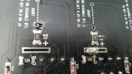
Also, I noticed a spot where one of the SMD capacitors on the bottom of the board near BT1 is missing, C57. Seems I may have a defective unit. What is the next step?
Thank you.
Ian,
Everything was looking good and working as designed. I went to measure the output voltages before connecting any loads. Batteries are charged and display reads "pending". I turned-on the unit, relays click, display reads "ON", time starts counting down. Then after 10 seconds the unit turns off and reads, "short protection". For that brief time it is on, there is 0 vdc at J2, J4, and also J8 reads 0, even though it is enabled in the settings. I do have 3.3 vdc output at J1 and 9.9 vdc at J3, however. ( 8 batteries are installed and the last 2 jumpers in place.)
Also, I noticed a spot where one of the SMD capacitors on the bottom of the board near BT1 is missing, C57. Seems I may have a defective unit. What is the next step?
Thank you.
I'm wondering how you've pulled this one off, Supersurfer? I planned to do this yesterday but when i saw the tightly packed string of lines running from TP16 (and companions) to ARM i got a little reluctant.
Would it be possible for you to make a few pictures of the cut and of the soldering on the bottom side connecting TP16 to L9? Thanks in advance
I would be happy to help you with pictures but this board is currently underway to Canada for repair because I misused it by disconnecting the lcd display cable while powered

It is not impossible to remove the copper pcb connection but a magnifier and a small exacto knife is needed, and a fixed hand.
Groeten,
I need some help please :
I assembled the LiFePO4 Battery power supply today and after I switched on , I realised high pitch radio freq noise output from the board . I checked all rails can output correct voltage . This radio noise only occurred when I switch ON the board with loading only . If I switch off (i.e. standby charging mode), the radio noise disappear . Just want to check anyone here have any idea what the problem is ?
Thanks for your help in advance .
This sounds like the same problem I had and it came from a bad quality smps. It did kill a sparkos opamp so be carefull.
I would be happy to help you with pictures but this board is currently underway to Canada for repair because I misused it by disconnecting the lcd display cable while powered
It is not impossible to remove the copper pcb connection but a magnifier and a small exacto knife is needed, and a fixed hand.
Groeten,
Ai, that's a costly mistake
i will find some bravery and make it work
Does it matter what side of the L9 i connect the 5v line to?
Ian,
Everything was looking good and working as designed. I went to measure the output voltages before connecting any loads. Batteries are charged and display reads "pending". I turned-on the unit, relays click, display reads "ON", time starts counting down. Then after 10 seconds the unit turns off and reads, "short protection". For that brief time it is on, there is 0 vdc at J2, J4, and also J8 reads 0, even though it is enabled in the settings. I do have 3.3 vdc output at J1 and 9.9 vdc at J3, however. ( 8 batteries are installed and the last 2 jumpers in place.)
Also, I noticed a spot where one of the SMD capacitors on the bottom of the board near BT1 is missing, C57. Seems I may have a defective unit. What is the next step?
Thank you.
I also have the LiFePO4 Mk II version and have a similar problem:
I initially installed 4 batteries into the BT 4,5 and BT 2,10 positions (for a desired output of 6.6v at J3 and J4) but after powering it up got a "short protection" display and the unit turned off.
I then realized I hadn't put the jumper wires in to short the empty cells so did this but still had the "short protection" advice on power up and the unit turned off again.
I wasn't sure if batteries should be in the BT6 and BT7 positions so installed these and had some success as the "short protection" warning has gone and I now have correct voltages at J1, J2 and J4 but 0v at J3 (should be 6.6v).
Anyone got any ideas why the initial "short protection" warning came up and perhaps this is related to the problems we are both having?
Thanks.
Actually, it says in the manual (section H) that BT6 & BT7 are required.
"A 26650 LifePO4 battery cell must be assembled for 3.3V voltage rail at J1/J2"Actually, it says in the manual (section H) that BT6 & BT7 are required.
Yes, I read that but at first thought it meant insert batteries for 3.3v outputs at J1/J2, not that these batteries at BT6 & BT7 are required for the other outputs to work as well.
@Heathkit and @marcus1, a few thoughts on your issues...
1. @Heathkit, can you post a picture of the missing C57 with some of the nearby components shown so others who have the MkII board can confirm the presence in their boards. Sorry, I don't have a MkII here, only a couple of the original ones.
2. Yes, AFAIK, BT6 & BT7 are required. I have powered the boards with NO cells installed and they stay powered for a few seconds and then drop out. They do this with no damage if anyone wants to try this themselves. I did not observe a message. I was not looking at the display, but instead using the on-time to trace connections for the jumpers.
3. I have one board with only BT6, BT7, BT2, and BT5 installed and appropriate jumpers installed so I get 4 3.3V outputs. It works ok that way.
4. Can you check your cell voltages both in the off state and when turned on before it cycles off. I wonder if one or more of your cells drop significantly or go to 0V, which would likely trigger the start up current protection circuit.
Curious what you find!
AND thanks @alazira for your great input on this!
Greg in Mississippi
DUAL POWER for I/V Input Board with LifePO4 Power Unit
STUPID QUESTION
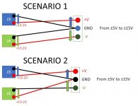
In which way I can realize the dual power supply needed by the IAN I/V board (+12 /0 / -12) with the LiFePO4 power Unit ?
I have to connect serially the output J3 and J4 connecting the two GND (-) togheter and the two positive, one on the +12 input and the other one to the -12V input (Scenario 1)
OR
I have to connect serially the output J3 and J4 connecting the positive of J4 with the negative of J3 and use the positive of J3 on +12V input and the negative of J4 into the -12V input (Scenario 2) as showned in the attached
STUPID QUESTION
In which way I can realize the dual power supply needed by the IAN I/V board (+12 /0 / -12) with the LiFePO4 power Unit ?
I have to connect serially the output J3 and J4 connecting the two GND (-) togheter and the two positive, one on the +12 input and the other one to the -12V input (Scenario 1)
OR
I have to connect serially the output J3 and J4 connecting the positive of J4 with the negative of J3 and use the positive of J3 on +12V input and the negative of J4 into the -12V input (Scenario 2) as showned in the attached
Attachments
@paoloilpizzo,
Your scenario 2 would work. Also see my post #247 at https://www.diyaudio.com/forums/pc-...essions-tweaks-mods-hints-25.html#post5779347
Your scenario 2 would work. Also see my post #247 at https://www.diyaudio.com/forums/pc-...essions-tweaks-mods-hints-25.html#post5779347
Ai, that's a costly mistake
i will find some bravery and make it work
Does it matter what side of the L9 i connect the 5v line to?
It does not matter on what side you solder the connection.
Plese let us know if it worked.
Good luck!
Just thinking out loud... what if the ultra capacitor PSU was an add on to the LifePO4 PSU, where that LifePO4 would charge the Ultra Capacitor bank when needed without requiring regulators since the LifePO4 cells would be used and when the cells are half way depleted or close, the LifePO4 charger would charge the cells? You would always have non-stop music of highest quality.
Just a thought...
Do
Just a thought...
Do
@Heathkit and @marcus1, a few thoughts on your issues...
1. @Heathkit, can you post a picture of the missing C57 with some of the nearby components shown so others who have the MkII board can confirm the presence in their boards. Sorry, I don't have a MkII here, only a couple of the original ones.
Greg in Mississippi
You can see C61 is present in similar position for the next battery, but C57 is missing, some residual solder sticking up as if it fell off before the solder hardened, not completely flat pads...
Attachments
STUPID QUESTION
In which way I can realize the dual power supply needed by the IAN I/V board (+12 /0 / -12) with the LiFePO4 power Unit ?
I have to connect serially the output J3 and J4 connecting the two GND (-) togheter and the two positive, one on the +12 input and the other one to the -12V input (Scenario 1)
OR
I have to connect serially the output J3 and J4 connecting the positive of J4 with the negative of J3 and use the positive of J3 on +12V input and the negative of J4 into the -12V input (Scenario 2) as showned in the attached
use scenario 2
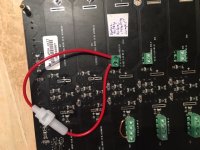
On the Mark II build I installed terminal blocks on the bottom side of the PCB. You can install the battery holder after, but must be careful not to install a jumper and battery at the same time! I consider using a fuse instead of a jumper for some safety in case of stupidity. This might be a good candidate:
https://www.mouser.com/datasheet/2/240/Littelfuse_Fuse_251_253_Datasheet.pdf-522535.pdf
https://www.mouser.com/datasheet/2/240/Littelfuse_Fuse_251_253_Datasheet.pdf-522535.pdf
Attachments
@Heathkit,
Thanks for the picture of the missing capacitor. Looking at it (and locating the similar ones in the original boards), I don't believe that capacitor is critical to operation.
To help us debug this, can you provide:
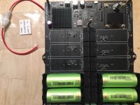
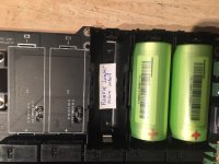
- A picture of your whole board from the battery side?
- The off, then on (before it clicks back off) voltage of each cell?
Also, the area around the jumper position above the resistor next to the missing capacitor looks odd. Did it get damaged or is that just an artifact of the photo?
Thanks!
Greg in Mississippi
Thanks for the picture of the missing capacitor. Looking at it (and locating the similar ones in the original boards), I don't believe that capacitor is critical to operation.
To help us debug this, can you provide:
- A picture of your whole board from the battery side?
- The off, then on (before it clicks back off) voltage of each cell?
Also, the area around the jumper position above the resistor next to the missing capacitor looks odd. Did it get damaged or is that just an artifact of the photo?
Thanks!
Greg in Mississippi
Thanks Greg for helping out on this. Yes, the photo has an artifact, the jumper area is fine. And I agree, looks like those SMD caps are for minor filtering and I doubt the missing C57 is causing the issues. I will take a few photos of the front of my board later tonight.
Over all, I would say the solder flow work on this board is not quite up to expected standards, at least comparing it to other boards I have from Ian or other group buys I have.
I did not see any change in voltage on the cells before and after attempting to turn the unit on several times and the unit running for 10 seconds then shutting off and displaying "short protection". I noticed that when it's off, all batteries on each side are connected in parallel, is that normal? So of course they all measure the same installed on the board, in my board 3.335 VDC. I will take them out and measure them individually later tonight. Btw, the first time I connected the power supply, it charged for maybe 20 or 30 seconds then went to "pending" and the green LED flashing, so it looks like my new batteries came fully charged.
- Home
- Amplifiers
- Power Supplies
- Develop ultra capacitor power supply and LiFePO4 battery power supply