Hi,
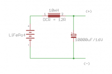
I'm curious if the LC filter (see schematic) at the LiFePo4 output could have positive impact on sound (eg by reducing high frequency noise).
I know that at the other side large capacitor may cause high inrush current which can be a challenge for relays (welding). Is it worth using LC, then?
Regards,
Attachments
Hi,
I'm curious if the LC filter (see schematic) at the LiFePo4 output could have positive impact on sound (eg by reducing high frequency noise).
I know that at the other side large capacitor may cause high inrush current which can be a challenge for relays (welding). Is it worth using LC, then?
Regards,
LC filter will degrade LifePO4 power supply performance. Avoid this configuration.
Please no worry about the large capacitance at the load side, my LifePO4 power supply has special designed delay scheme to protect relays from welding.
Regards,
Ian
ultra capacitor power supply 1st prototype PCB order placed. You will see it soon.
Regards,
Ian
HI Ian
While I would love to own both, I can't afford both the LiFePO4 PS and the Ultra-cap PS.
Do you envisage the Ultra-cap PS will be ready for the next group buy (along with the LiFePO4 PS) or unsure as yet?
Thanks
HI Ian
While I would love to own both, I can't afford both the LiFePO4 PS and the Ultra-cap PS.
Do you envisage the Ultra-cap PS will be ready for the next group buy (along with the LiFePO4 PS) or unsure as yet?
Thanks
Thanks marcus1 for your interest.
My LifePO4 power supply project are finished. But the ultra capacitor power supply is still under developing. So I'm afraid it can not catch up with this time. You will need more patience if your are waiting for it.
Regards,
Ian
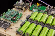
This looks great Ian!
Any chance you could share couple of more pictures of this setup from different angles to understand the wire routing?
@syracuze
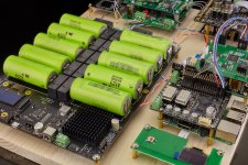
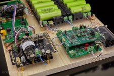
More pictures from different angles.
Ian
Attachments
Last edited:
It's just a spdif interface, noting special. So, no worry.
I'll do a interface board with everything integrated later when I get time. It's just a functional verification for now. I don't have problem.
Regards,
Ian
There is a cheaper board that can be integrated with 5 sets of inputs that are 2 coaxial, 1 fiber, 1 AES, 1 IIS/DSD input and Amanero's USB.
Https://item.taobao.com/item.htm?id=520832497451
ultra capacitor power supply 1st prototype PCB order placed. You will see it soon.
Regards,
Ian
That is great news Ian!
Cheers!
Alex
It's a very good question.
Because all ultra capacitor rails are isolated from each other, so theoretically, yes, you can.
The alternatively solutions would be using bigger ultra caps, such as 3000F, or having them parallel externally.
I'll try some 26650 holders to see if thy can fit.
Regards,
Ian
Sorry for the confusion Ian, I actually was talking about the 26650 PSU's
Since I read that your upcoming UltraCaps psu's deliver only between 1.8V and 5V, I was thinking on using 26650 psu's for pre-amp instead of Ucaps psu's because I need voltage +/- 12V to 15V Or is it possible to reach +/- 12V~15V with your Ultracap psu design?
About output voltage range Ultracap psu's in common, It would be rather nice to extend the lower Voltage threshold to 1.2V This would make the psu's more compatible with newer electronics which possibly operate at lower voltages. And, at the high threshold, I really would like the option for higher voltages for usage in ClassD amps or driverstages of poweramps. Not sure if you ever tried feeding a driverstage in poweramp with very clean supply, it really makes a huge difference in sq.
For high voltages there would be need of many ultracaps to reach those voltages, which would result in excessive switching between the banks, but when using mosfets and big buffer elco at output, (or at input at host / driverstage poweramp / ClassD amp), there's no problem at all with very short switching times.
Just thinking on making them as usefull as possible for all our audio needs
")
Cheers Ian,
Alex
There is a cheaper board that can be integrated with 5 sets of inputs that are 2 coaxial, 1 fiber, 1 AES, 1 IIS/DSD input and Amanero's USB.
Https://item.taobao.com/item.htm?id=520832497451
+1
I got this board and it works very good.
It is hard to solder the battery connector by hand and it is very easy to burn the battery. I have burnt four batteries, and the result is poor welding quality and not secure enough. The conclusion is that you should someone help you to solder using the Spot Welding.
Last edited:
It is hard to solder the battery connector by hand and it is very easy to burn the battery. I have burnt four batteries, and the result is poor welding quality and not secure enough. The conclusion is that you should someone help you to solder using the Spot Welding.
I heard somebody using ultra capacitor doing this kind of job. Worth to give a try.
YouTube
Ian

I didn't expect it to be that simple. I just ask the store that sells the battery, according to my needs, help me solder for free charge.
The method of this video may be relatively safe.
YouTube
Last edited:
Hi,For a 350F ultra capacitor, roughly can last around an hour, at 35ma, 5.25-4.75.
Regards,
Ian
Does it mean two 2.7V/700F in series?
Regards, B
This is a very nice project and I don't mean to criticise, but...
Noise perfomarnce of LiIon (and most likely LiFePO4) cells varies with state of charge:
(PDF) New methodology of electrochemical noise analysis and applications for commercial Li-ion batteries
All LiIon technology is very temperature sensitive and "wears out" over time/use. At least the characteristics are generally best at room temp and the load cycling in this application should keep the cells in the best range for longevity.
Earlier in the thread it was stated that the load transient response is excellent and o/p impedance is very low (4mOhms?). Has anyone done any measurements? I thought the chemical reactions were relatively slow.
Of course the galvanic isolation benefit is indisputable and is probably helpful due to the modular setup of the system.
Anyone got any measurements of load transient response?
This is a very nice project and I don't mean to criticise, but...
Noise perfomarnce of LiIon (and most likely LiFePO4) cells varies with state of charge:
(PDF) New methodology of electrochemical noise analysis and applications for commercial Li-ion batteries
All LiIon technology is very temperature sensitive and "wears out" over time/use. At least the characteristics are generally best at room temp and the load cycling in this application should keep the cells in the best range for longevity.
Earlier in the thread it was stated that the load transient response is excellent and o/p impedance is very low (4mOhms?). Has anyone done any measurements? I thought the chemical reactions were relatively slow.
Of course the galvanic isolation benefit is indisputable and is probably helpful due to the modular setup of the system.
Anyone got any measurements of load transient response?
I bought a battery, from Taobao, which internal resistance is equivalent to A123 and the price is only half of A123. I bought 10 batteries and the test results were almost 5mohms.

https://www.diyaudio.com/forums/pow...epo4-battery-power-supply-33.html#post5626853
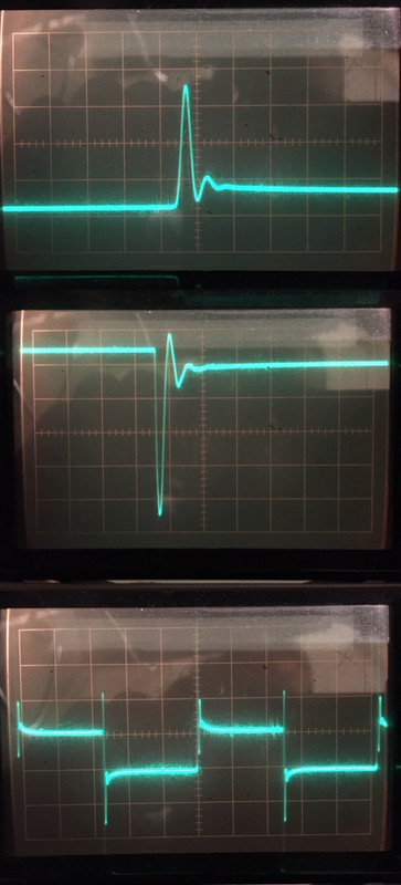
Further to my post #396, I have done some measurements on the LiIon batteries that I use for my cycling lights.
The battery consists of 3 LiIon 18650 cells in series to provide 11.5V. A protection circuit is included but I put the 'scope probes on the battery terminals, thereby excluding the effect of the protection circuit for the waveforms.
With a 10KHz 50% duty cycle i switched 2 test currents: 56mA and 460mA. The waveforms are for the 56mA load, although they are very similar at both currents.
1st and 2nd waveforms are magnified views of the 3rd scope shot.
1 & 2 are at 2uS & 50mV/div
3 is at 20uS & 20mV/div
My estimate of the output impedance of the battery is 420mOhms, that's 140mOhms per cell. The load transient response indicates some (internal) inductance interacting with the output impedance.
I do realise that these are not LiFePO4 cells, but are they much better?
As it stands, I am a bit concerned about the proposed battery PS.
Last edited:
Further to my post #396, I have done some measurements on the LiIon batteries that I use for my cycling lights.
The battery consists of 3 LiIon 18650 cells in series to provide 11.5V. A protection circuit is included but I put the 'scope probes on the battery terminals, thereby excluding the effect of the protection circuit for the waveforms.
With a 10KHz 50% duty cycle i switched 2 test currents: 56mA and 460mA. The waveforms are for the 56mA load, although they are very similar at both currents.
1st and 2nd waveforms are magnified views of the 3rd scope shot.
1 & 2 are at 2uS & 50mV/div
3 is at 20uS & 20mV/div
My estimate of the output impedance of the battery is 420mOhms, that's 140mOhms per cell. The load transient response indicates some (internal) inductance interacting with the output impedance.
I do realise that these are not LiFePO4 cells, but are they much better?
As it stands, I am a bit concerned about the proposed battery PS.
Generally, the electrolyte of a lithium ion battery is liquid, but a lithium polymer that has been developed later is superior to a lithium ion battery of a liquid electrolyte.
- Home
- Amplifiers
- Power Supplies
- Develop ultra capacitor power supply and LiFePO4 battery power supply