The effective ESR of a good regulator will be in the single digit miliohms in the audio frequency range.
I designed a regulator with a theoretical impedance in the nano-pico ohms between 1hz-20khz.
Sounds interesting - perhaps you would consider sharing details with the DIY community?
Cheers
Whit
Not meant to be a link. The article is behind a pay-wall at Linear Audio All articles | Linear Audio. The cost is 3 of those euro things. Well worth it IMHO.Is that meant to be a link? If so it doesn't work.
George
Looks like a very interesting project.
Unfortunately, I have eardrum damage, so I will never hear the difference, but I like it from a technical perspective. My son probably can, so that is why I am on this forum.
When using a power supply like this for audio applications, is it assumed that the max load frequency is audio range (20 ish kHz) or more like 10 X that number?
But they are so used. See, e.g. Guardian-86: Speaker protection board for LM3886-based amplifiers (and others). Note the graph of THD+N.Not sure I trust mosfet on-state linearity though. There's a reason they aren't used as relays at the output of amplifiers.
Yeah I plan to once I get around to building a more refined prototype and done some more testing. Currently I'm swamped with finishing another of my designs.Sounds interesting - perhaps you would consider sharing details with the DIY community?
Cheers
Whit
Thanks for the link.But they are so used. See, e.g. Guardian-86: Speaker protection board for LM3886-based amplifiers (and others). Note the graph of THD+N.
I wouldn't mind using such a mechanism at the output of an amplifier in a fb loop, just not as an open loop relay at such a sensitive node as AVCC.
Then again the article mentions mechanical relay distortion, what are the potential distortion mechanisms for a mechanical relay? Seems odd that they would produce any.
Last edited:
But they are so used. See, e.g. Guardian-86: Speaker protection board for LM3886-based amplifiers (and others). Note the graph of THD+N.
They appear to be using Infineon 027N10N mosfets. The datasheet is here.
These are 100 Volt, 120 Amp, 2.7mOhm Rdson units. The Vgsth is pretty high, though (2.7 Volts), so would not work as well as the TI CSD17312 in a 3 Volt battery circuit (Vgsth is 1.1 Volts), previously mentioned. The CSD17312 is only rated to 30 Volts, but that's fine for the current discussion topic and Rdson is less than 2mOhm. Datasheet is here.
Cheers
Whit
Last edited:
Yes - I think it would be good. The best-case ESR for a LiFePO4 cell is about 34 mOhm, depending on state-of-charge and temperature, so the 2 mOhm contribution of the mosfet is not too bad. And if this is regarded as too high, two or more could be paralleled, I would think.
Supercaps (the best ones) are in the same ballpark as far as ESR goes.
As a reference, bear in mind that 1 foot of 24 gauge AWG stranded wire has a resistance of about 25 mOhms at room temperature and the same is true for a 2 inch-long 1mm-wide 1 oz PCB copper trace.
Cheers
Whit
100% agreed with you.
I've noticed the PCB trace resistance issue already when I tested charging the LifePO4 cells at 10A. Exactly as what you mentioned.
I need to use 2 oz copper for PCB V2.0, as well as make copper area as big as possible. Will increase the cost a little bit but it worth it.
Regards,
Ian
Last edited:
this is certainly a lot awaited by me but I believe by many users............................
However, if your DAC chip takes 5V internally, you have to wait for my ultra capacitor power supply which will have pure 5V output.
Regards,
Ian
For example, on my DAC diy I use a pair of PCM1704 and the I/V is implemented with the OPA861 both in conversion and in the buffer (powered by + - 5V).
So I would need at least two dual 5V lines. Rather I would also need two more lines for the JLSounds i2sOverusb card. Currently I feed everything with LDO LT3045 with great satisfaction ...... but I am sure that the solution with Ultracapacitors can be a big step forward
this is certainly a lot awaited by me but I believe by many users.
For example, on my DAC diy I use a pair of PCM1704 and the I/V is implemented with the OPA861 both in conversion and in the buffer (powered by + - 5V).
So I would need at least two dual 5V lines. Rather I would also need two more lines for the JLSounds i2sOverusb card. Currently I feed everything with LDO LT3045 with great satisfaction ...... but I am sure that the solution with Ultracapacitors can be a big step forward
Then, the down the road ultra capacitor power supply will exactly meet your application. But an ultra capacitor power supply can not be integrated as compact as a LifePO4 power supply because of the multiple banks will be included. Two or three rails per board is possible. But have to bridge them together if more voltage rails are required. Thus cost will also be increased. But any way, sound quality is the most significant thing.
BTW, according to my design idea, the LifePO4 power supply and the ultra capacitor power supply can also be bridged to work together.
Regards,
Ian
Last edited:
Attachments
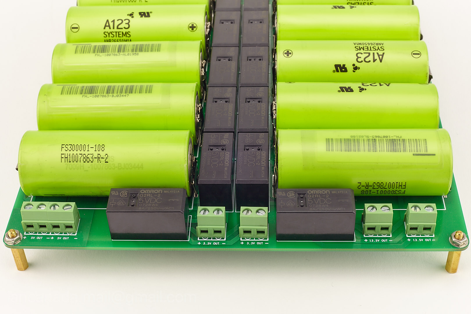
LifePO4 battery source
I recently bought a used LifePO4 battery pack with 96 cells local in Toronto. I've tested some of them and didn't find any difference to the new ones. The seller said that the battery pack was routine retired from hybrid TTC bus. Seems they were widely used by vehicles and not difficult to find used with good price.
I also bought some new ones a couple of years ago from this German supplier. The price was reasonable but still much expensive than the used ones.
a123 : A123 Systems APR18650M1A 1100mAh - A123 Systems AMP20M1HD-A, 2
There are two versions of A123 26650 battery cell. The ones from my battery pack are mode A, and those on the German website are mode B. Google searching result says that mode A has bigger current than mode B but I didn't find any difference.
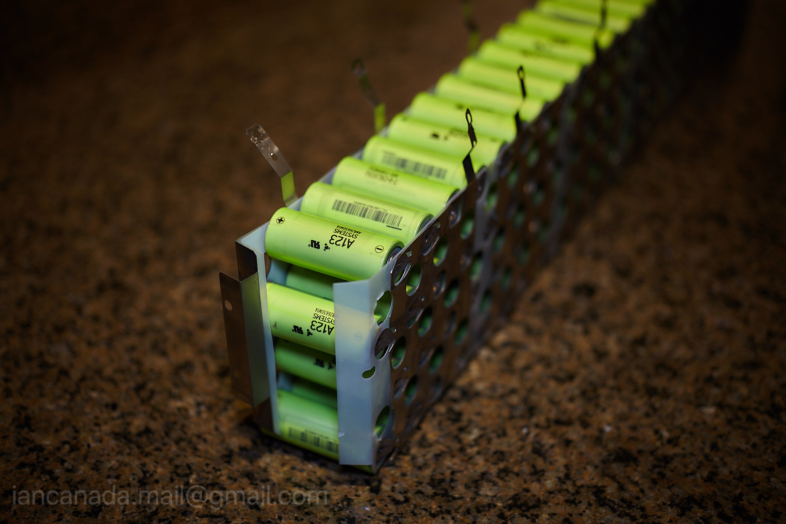
LifePO4BatteryPack by Ian, on Flickr
Ian
I recently bought a used LifePO4 battery pack with 96 cells local in Toronto. I've tested some of them and didn't find any difference to the new ones. The seller said that the battery pack was routine retired from hybrid TTC bus. Seems they were widely used by vehicles and not difficult to find used with good price.
I also bought some new ones a couple of years ago from this German supplier. The price was reasonable but still much expensive than the used ones.
a123 : A123 Systems APR18650M1A 1100mAh - A123 Systems AMP20M1HD-A, 2
There are two versions of A123 26650 battery cell. The ones from my battery pack are mode A, and those on the German website are mode B. Google searching result says that mode A has bigger current than mode B but I didn't find any difference.
LifePO4BatteryPack by Ian, on Flickr
Ian
Sent you a PM with a link to a paper regarding estimating SOC for LiFePO4 cells.
Cheers
Whit
Sent you a PM with a link to a paper regarding estimating SOC for LiFePO4 cells.
Cheers
Whit
Thanks Whit,
Good reference, saved.
Regards,
Ian
Is there a reason you can't just switch on a voltage regulator when the battery or capacitor gets too low instead of using relays?
The voltage regulator can simply be disabled while the battery/capacitor is powering the DAC, then when the battery/capacitor gets too low the voltage regulator switches on and continues to power the DAC while charging the devices.
The sound may not be as good during the charging process but at least the device is not off and you get to avoid using relays or mofets.
Am I missing something?
- Home
- Amplifiers
- Power Supplies
- Develop ultra capacitor power supply and LiFePO4 battery power supply