
arent some of the skelcap values available in the more standard axial arrangement?
As for your problem; I would grab yourself some copper buss-bar stock that is about the same thickness as the nub is tall, drill a hole very slightly smaller than the protruding nub and use a rubber mallet or similar to softly tap it onto the terminal. the copper is soft and malleable and should tap right on; I reckon you could get a good connection without solder. Then use whatever method you want to connect the bussbar to the PCB. perhaps with a thick wire soldered to it, , but if doing that, solder to the bussbar first, before fitting, as otherwise the copper and ucap will wick away too much heat. (or just drill a hole and attach with bolt and ring terminal)
you could also do the same thing with a alloy or copper substrate PCB, like those used for high power LEDs (and recently a few adapter PCBs for SMD mosfets here).
Last edited:
Okay, thanks. This will be my new Plan A (drilling it for the Eatons).
I'll consider the cooper bar idea after I place an order, but Plan A may move to the top now.
The SkelCaps do have what we want. The problem is they are in such demand that Government Services (Infrastructure) and Fortune 500 companies gobble up all the stock.
I'll consider the cooper bar idea after I place an order, but Plan A may move to the top now.
The SkelCaps do have what we want. The problem is they are in such demand that Government Services (Infrastructure) and Fortune 500 companies gobble up all the stock.
Hello,
I am in the process of connecting the lifepo4 board to my fifopi tower.
I installed 4 cells to make 4 separate 3,3 volts.
Right now i just need two 3,3 volts , one for each side of the fifopi. AND i will have one 3,3 volt for the reclockpi. The Sinepi will get its power from the fifopi board.
These 3 cells all have their own UcHybrid board.
So there is one 3,3 cell not used. Can i put that cell in parallel with one of the other cells by just soldering a thick wire from soldetab to soldertab?
If this cannot be done i better remove the cell by cutting the tabs.
I can imagine that the biggest consumer of energy could benefit from a cel in parallel.
Greetings,Eduard
@eduard,
I answered you question here:
https://www.diyaudio.com/forums/dig...mate-weapon-fight-jitter-760.html#post6871738
Ian
I answered you question here:
https://www.diyaudio.com/forums/dig...mate-weapon-fight-jitter-760.html#post6871738
Ian
Hats off to @iancanada for the UcPure boards - thank you very much.
I've just constructed my first one and apart from completely ignoring the size of the UCs during the purchase (they are BIG) and the fact that one of my kids asked me if I was building a bomb...all is looking good ;-)
I've built 15v one so far, to power Andrea's clocks. See attached pics. I got slightly worried as the 'full' LED came on but the charge went past 15v without stopping(!) but it's levelled out at 15.5v and is now constant.
Once I've got this one installed I've got 2 more. One is going to power the SinePI once I get it working properly in my setup.
Here are some pics of the test build and I will report back when I'm powering something I can listen to!


Thanks again Ian,
Crom
I've just constructed my first one and apart from completely ignoring the size of the UCs during the purchase (they are BIG) and the fact that one of my kids asked me if I was building a bomb...all is looking good ;-)
I've built 15v one so far, to power Andrea's clocks. See attached pics. I got slightly worried as the 'full' LED came on but the charge went past 15v without stopping(!) but it's levelled out at 15.5v and is now constant.
Once I've got this one installed I've got 2 more. One is going to power the SinePI once I get it working properly in my setup.
Here are some pics of the test build and I will report back when I'm powering something I can listen to!
Thanks again Ian,
Crom
Hello Crom,
They could act like a bomb once someone wearing a ring/watch will try to check the weight of your construction.
IF i am right there will always be a minimum charge in them so once you have connect them to a power supply you should take some extra care.
Better have the terminal '' area '' protected with a kind of plastic board.
And it looks like the UCpureboard is a bit bent because of the tie-raps. Maybe '' introduce '' a more sturdy board to mount the ucpure board upon and then use the sturdy board to attach the tie raps..
The Sinepi will take its power from the Fifopi board so that will give you the advantage of just having to use one UCpure package.
I just finished my lifepo4 and put it in my DDDAC. Looks like a Christmas tree!!
If i would trash the lifepo4 i would probably replace it with one UCpure for the clean side '' feeding '' fifopi, reclockpi and Sinepi.
One lifepo4 mini 3,3 volt for the '' dirty '' side of the Fifopi assisted with an Uchybrid board
One 5 volt supply for the raspberry. There i already have the 5 volt conditioner . Wont have much space to locate a big circuit so a pretty 5 volt standard supply will do.
BUT first wait and see if my construction works at all after building the Italian clock circuits with Doede's intelligent circuit feeding it.
Greetings, eduard
Attachments
Hello,
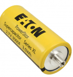
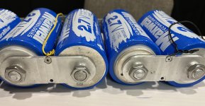
This one shows 2,7 volts but for 5 volt supply i would go for 3 volt to create a bigger safety margin. I think Ian used two 2,7 or 3 volt caps in series to create a 3,3 volt supply without balancer.
Of course at the end of the cable there should be a cable lug/terminal lug because just stripping the cable, put the bare copper under a washer/nut combination and fasten it will damage/break individual wires. It could well be that a cable lug with a smaller diameter but properly used by using the threaded bushing at the end of the terminal would create a better/safer contact.
Greetings, eduard
Attachments
Hello,
Two times 2,7 is 5,4 for sure!
In the future i might start using an UcPure with 3,3 volt and i am going to use 3 volt ultracaps because i will not use a circuit to keep each cap at an identical voltage.
For a 5 volt supply with 2,7 volt caps i would use a balancing circuit. If one of the two caps '' ages '' differently you MIGHT end up with one cap getting a bit to much without a balancer.
Maybe just change your order into two 3 volt caps
Greetings, Eduard
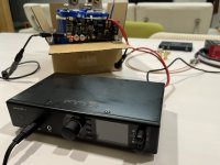
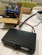
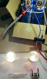
I spent a little time asking Taobao sellers to provide the ultracapacitors as shown in the picture below. Unlike usually they will give recycled products that are welded together with lasers, and use awkward methods to weld the balance board. After installing UcPure, use homemade halogen. After the lamp discharger has been charged and discharged several times but still no problem, connect it to the ADI-2 DAC (I currently only have it to use 15v DC). Use HD660s earphones for listening. It is difficult to distinguish the obvious difference from the original power supply. Described as the difference between whiskey in 12 years and more years, this power supply system is too large, so I still use the original power supply.
Attachments
Hello,
I think in order to get the best results you should use new parts from dealers like Mouser. If you buy these as used parts from a Chinese website it is well possible that the cap even when new was already a bit " dodgy" . After that a few months or years of abuse and it will be even worse.
Greetings,Eduard
I agree with you. I just want to try the effect of ultracaps. I will give it aside for such a huge power supply device. It may be more elegant to use battery power because of its size, but it also satisfies my initial understanding of ultracaps. I used ichager 206b to charge it with 10A, it can reach 12.5V in a few minutes without any heat, and then discharge to 0.1V without any problem.Hello,
I think in order to get the best results you should use new parts from dealers like Mouser. If you buy these as used parts from a Chinese website it is well possible that the cap even when new was already a bit " dodgy" . After that a few months or years of abuse and it will be even worse.
Greetings,Eduard
Note. During the use of UcPures, I accidentally switched s1 to off, causing the voltage to exceed the preset voltage, and the balance board lights up red. I don't know if it is a special case or there will be such a phenomenon.
Hi Ian,UcConditioner load transient response testing result
Power supply manufacturers normally don't show you this waveform because it looks ugly. This is the output from a LT3042 ultra low noise regulator (with high current extension). Yes, it’s true! The 0.8uVRMS was measured at static condition with pure resistor load. However, in the real applications, this condition will never exist, load demand is always dynamic. That's why I did this load transient response test.
The top waveform shows the original output of the LT3042 5V regulator with load demand current changing between 100mA to 1A every 500us. The ripple is at 50mV - 100mV level. It causes by the feedback (PID) control of the active regulator power supply.
The bottom waveform shows the same LT3042 5V regulator under same test condition but with UcConditioner added in parallel. It was measured at UcConditioner output. Did you see how much improvement it makes?
The 1A load transient response ripple is almost disappeared! Only some high frequency spurs left which was caused by the inductance of the wires of the load at moment of switching.
The ultra capacitors I used on the UcConditioner were BCAP0325 P270 S17. Their internal ESR is only 1.7mohm. Have to use wires as big as possible in this case because the wire resistance could be higher than the ultra capacitors. Smaller wires will degrade the performance of UcConditioner for sure.

UcConditioerLoadResponse by Ian, on Flickr
Ian
Nice comparison you have here. I was wondering if the same benefit would be had if I would place the UC before the LDO which is close to the dac?
So for example: linearpi>UcConditioner>LT3045
In the DDDAC thread I saw people using the UcConditioner in series to power the dac boards.
Is it possible to power two 5v UcConditioners in parallel with one 5v PSU (provided there is sufficient current), and connect the application in series with the UC to get 10v out of the UcC?
Thanks,
Robin
Hello,
I know Supersurfer made a 10 volt supply for his Etherregen using UcConditioner boards. But then you will need two 5 volt regulator boards each with a separate transformer winding.
I am not sure that adding a series regulator after the ultracaps will give benefits. I think that the Tent shunts would be a more '' logical solution ''
It seems Ian has '' left the building '' so maybe Stefan( supersurfer) can give you some nice ideas.
greetings, eduard
Hi,
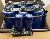
Eduard has answered your question correctly; it is important that you use 2 separate secondaries for feeding the two linearpi’s With ultracaps. The outputs can be put in series to get the 10v. I would not use a regulator behind the ultracaps, it will diminish their effect.
I also recommend not to use any more voltage regulation than strictly necessary in the raw power supply for a dddac. The local regulation (Tent shunts for the newer pcb’s) are sufficient and the results with.
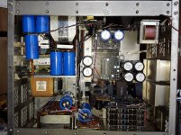
This is a picture of a power supply I use for an Etherregen.

Eduard has answered your question correctly; it is important that you use 2 separate secondaries for feeding the two linearpi’s With ultracaps. The outputs can be put in series to get the 10v. I would not use a regulator behind the ultracaps, it will diminish their effect.
I also recommend not to use any more voltage regulation than strictly necessary in the raw power supply for a dddac. The local regulation (Tent shunts for the newer pcb’s) are sufficient and the results with.
This is a picture of a power supply I use for an Etherregen.
- Home
- Amplifiers
- Power Supplies
- Develop ultra capacitor power supply and LiFePO4 battery power supply