You can verify your Qx version here:
Asynchronous I2S FIFO project, an ultimate weapon to fight the jitter
Glad you found your sweet spot. You may want to check if removing the LDOs, going 3.3V and adding a UcConditioner 3.3V on J5 will help further.
I started from the Q3 so not aware of the Q2 optimisations.
Asynchronous I2S FIFO project, an ultimate weapon to fight the jitter
Glad you found your sweet spot. You may want to check if removing the LDOs, going 3.3V and adding a UcConditioner 3.3V on J5 will help further.
I started from the Q3 so not aware of the Q2 optimisations.
Happy Listening.C. FifoPi Q3 new improvements
Uses pure 3.3V for a clean side DC power supply. All LDOs have been removed to allow direct operation with
a better 3.3V power solution via LifePO4 or ultra capacitor.
Last edited:
Ian, I have two 5v UcConditioners I have been trying to set up for a DAC. I have an LT3045-based power supply feeding the DAC and a Salas Ultrabib feeding the reclocker. When I tried using one 5v UcConditioner on the output of the Ultrabib only the red power light turns on - the yellow power good light was not coming on after waiting a bit. I tried with a Reflektor D and had the same problem. I then tried with an L adapter power supply and got the yellow light. After a few minutes, the blue and green conditioning lights came on.
However, not long after that, the D6 overvoltage indicator light came on. I tried swapping the UcConditioners before and seemed to have the same issue with the other (the yellow power good light not coming on). Maybe I should have left it longer, but I was worried about the D6 light.
Do you have any suggestions?
Attachments
As a follow-up to the above, when the UcConditioner is connected to the ultrabib I measure approx. 4.7vout on the ultrabib when it's usually set to 5v. Once connected to the UcConditioner, I'm not able to adjust the vout of the Ultrabib. For some reason, it seems locked into this output. I suspect that because the voltage is low, the yellow power good light will not illuminate.
Salas Ultrabib works OK for me.
Is this working?
1. Verify that you have 5v on Ultrabib output when nothing connected to it.
2. Remove power to Ultrabib and connect it to UcConditioner (nothing connected at UcConditioner output)
3. Power up Ultrabib.
4. Don’t know how much current you have through your Ultrabib, but I think I waited 10-20 min to get UcConditioner fully charger and all diodes lights up OK. While you wait you can check at Ultrabib output if voltage slowly increase towards 5V.
5. If all good and you get 5v, power of Ultrabib, connect UcConditioner to a load and power up Ultrabib again
Regards Micke
I tried re-connecting it to the Ultrabib and all seems okay now. The D6 light was very faint for a bit but has turned off. Not sure what was going on, but I was getting the light even using the linear pi power supply. Voltage is now 5v out of the Ultrabib - I'm not sure if it would sag as the ultracaps are charging but it was odd that I couldn't adjust the voltage when connected.
Bass is a bit stronger when using the UcConditioner on the cronus reclocker. The MPA audio LT3045 power supply had a similar effect when I first tried it on the DAC. UcConditioner sounds good there too, maybe not as big as a jump because that supply is already pretty low noise. The top-end remains a big bright on the Buffalo DAC even when using the legato. I'm going to keep experimenting with either running a 5v UcConditioner and powering AVCC separately or maybe directly with a 3.3v UcConditioner. If I can tone down the brightness it will sound very good.
Once a new Amanero comes, I will compare it against Ian's fifopi and ESS Dual Mono DAC stack.
Last edited:
Hello Ian,
When I change the ac power cable, the sound still comes out sounding different.
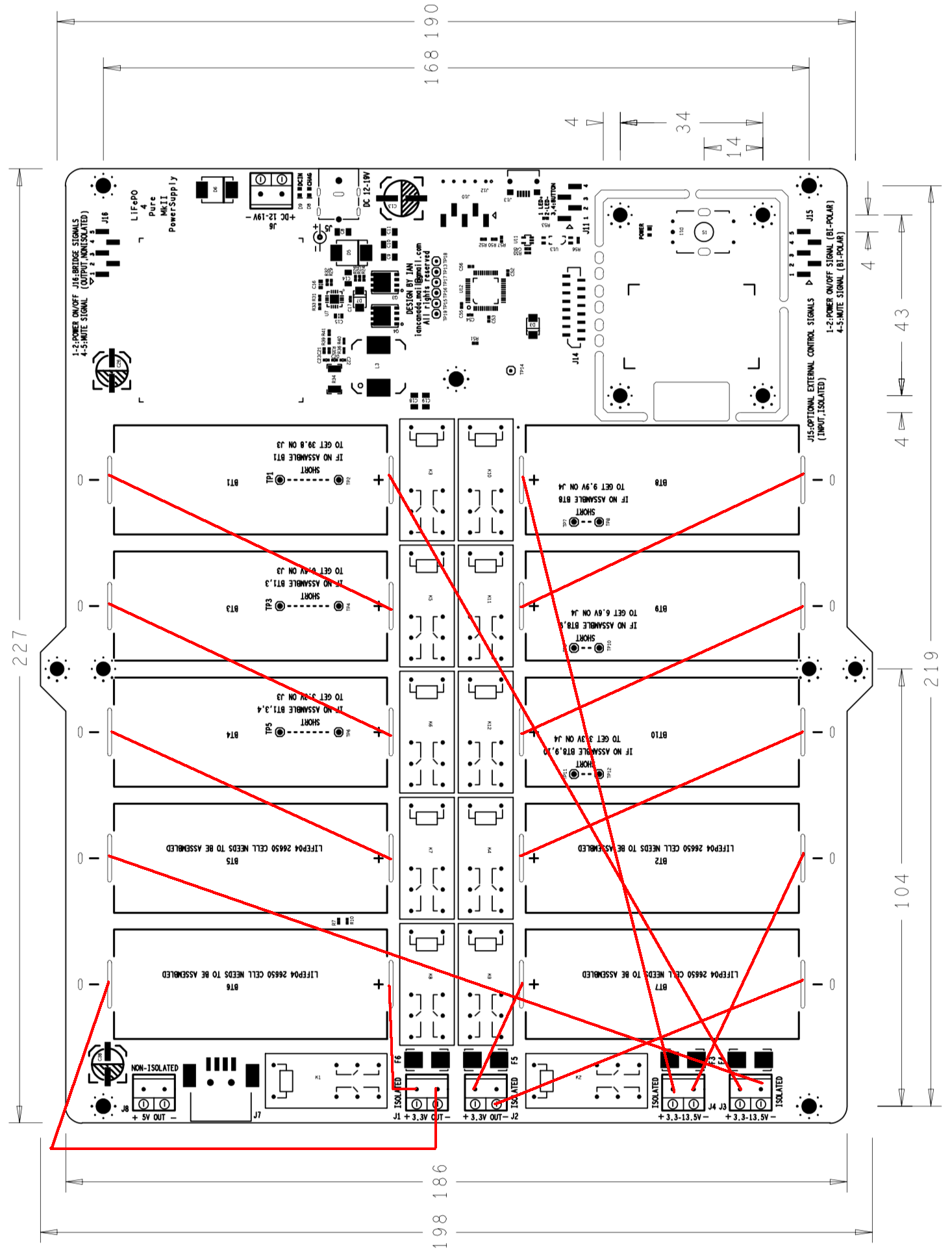
The j3/j4 13.2v output rail is isolated from the dc input line even when checked with a tester.
If so, it should be pure battery output, but why is there a difference in sound?
Even if you disable the 5v rail, the ground is still active.
Could it possibly be the ground 5v rail ground causing the sound to change?
Usually I use 18awg ac cable, but with 14awg ac cable
If you change it and then test it, the difference clearly shows.
Both smps power and linear power sound different when I switch the ac cable.
Then everything related to the dc input is related to the difference in sound.
This can't be coming straight from battery output.
Are there any solutions that can definitely solve this problem?
I connected and tested like so:
power outlet > linear power supply > MKIII Batteries Power Supply (J3 / J4)> DAC> USB> mobile phone or pc or tv box"
When I change the ac power cable, the sound still comes out sounding different.
The j3/j4 13.2v output rail is isolated from the dc input line even when checked with a tester.
If so, it should be pure battery output, but why is there a difference in sound?
Even if you disable the 5v rail, the ground is still active.
Could it possibly be the ground 5v rail ground causing the sound to change?
Usually I use 18awg ac cable, but with 14awg ac cable
If you change it and then test it, the difference clearly shows.
Both smps power and linear power sound different when I switch the ac cable.
Then everything related to the dc input is related to the difference in sound.
This can't be coming straight from battery output.
Are there any solutions that can definitely solve this problem?
I connected and tested like so:
power outlet > linear power supply > MKIII Batteries Power Supply (J3 / J4)> DAC> USB> mobile phone or pc or tv box"
Hi Ian,
Everything is going well with the MKIII, I'm at 6/10 soldering battery holders. I should be 10/10 after the weekend. Thanks for including extra fuses. I ended up needing one.
I started wondering also how I will power the MKIII in the long run. I just realised a month or so ago that 5V is not battery-powered so I'm concerned about mains issues like the post above mine.
Since I have extra 26650, I was considering a third-party BMS. Also considering another 12V/20A non-A123 LiFePO4 battery which would make it completely off the grid.
But I think the most optimal is to grab another MKIII and running parallel 16.5V into the DC-IN of my current MKIII. It will not be bridged.
Please let me know if this is possible. Too much power from 16.5V => MKIII(2) (Amp-wise, not voltage)?
Thanks. Enjoying the DIY grind.
Everything is going well with the MKIII, I'm at 6/10 soldering battery holders. I should be 10/10 after the weekend. Thanks for including extra fuses. I ended up needing one.
I started wondering also how I will power the MKIII in the long run. I just realised a month or so ago that 5V is not battery-powered so I'm concerned about mains issues like the post above mine.
Since I have extra 26650, I was considering a third-party BMS. Also considering another 12V/20A non-A123 LiFePO4 battery which would make it completely off the grid.
But I think the most optimal is to grab another MKIII and running parallel 16.5V into the DC-IN of my current MKIII. It will not be bridged.
- MKIII(1) - 10 A123 @16.5V all single rail => MKIII(2)
- MKIII(2) - 4 A123 @ 4 X 3.3V. 1xUCMateConditioner 3xUCHybrid
Please let me know if this is possible. Too much power from 16.5V => MKIII(2) (Amp-wise, not voltage)?
Thanks. Enjoying the DIY grind.
Last edited:
Then everything related to the dc input is related to the difference in sound.
This can't be coming straight from battery output.
Are there any solutions that can definitely solve this problem?
I connected and tested like so:
power outlet > linear power supply > MKIII Batteries Power Supply (J3 / J4)> DAC> USB> mobile phone or pc or tv box"
I suspect what you are hearing here are second order effects to do with the grounding scheme of your system. Everyone knows noughts and ones are just that. Bit perfect is easy right?... but there is so much more going on than that. I find it helpful not to think of system elements as discreet boxes that have no relationships to one another. They are all interconnected and interacting both through interconnects and also your AC power supply. My hunch is your digital sources are likely to be producing a lot of high frequency radio spectrum noise. This does not behave like DC. It can crawl everywhere through power supply and interconnects. How do you solve this? I'd look upgrading your digital source to something that is optimised for audio. The ones and noughts will be the same but all the second order effects, like RF crawling through the power supply, should be much better.
@mixmaster: it is a true battery supply, the outputs (except the +5V) are all fully floating and not connected to anything else when it is switched on. The DC input just powers the management microcontroller when not charging. Do you have the expected voltages at each of the outputs when the board is switched on? If yes, then it is working correctly.
Hi Ian,Hi Ian,
Please let me know if this is possible. Too much power from 16.5V => MKIII(2) (Amp-wise, not voltage)?
Please ignore post #1430. I almost pulled the trigger on a non-A123 LiFePO4 battery pack to power the MKIII, but came to my senses.
I was only worried about 5V mains, not if the battery rails were not isolated. I'm confident the battery rails are isolated as that seemed to be a design decision before rolling out.
My plan is to remove the RPI from the mix and go RPI-less with a ReceiverPi @3.3V.
- ReceiverPi @3.3V
- FiFoPi Q3 @3.3V Clean Side
- TransportPi @3.3V
Cheers
Last edited:
Thanks for the Salas Ultra BIB suggestion.
I'm all over the place with these Ian projects, but I think I narrowed down my plan.
Initially, I was just going to power the MKIII with this:

This will allow me to be completely off the mains, but maintaining multiple batteries may not be good long-term.
So I'm determined now to go with a 12V source and remove the RPi 5V out of the equation.
So desktop:
I'll allocate my other current parts to a Transport:
Makes more sense than grabbing another LiFePO4 battery or another power supply and I'm able to avoid 5V mains on both systems.
I'm all over the place with these Ian projects, but I think I narrowed down my plan.
Initially, I was just going to power the MKIII with this:
This will allow me to be completely off the mains, but maintaining multiple batteries may not be good long-term.
So I'm determined now to go with a 12V source and remove the RPi 5V out of the equation.
So desktop:
- MKIII 13.2V/12V to 12V source
- ReceiverPi @3.3V
- FiFoPi Q3 @3.3V
- TransportPi @3.3V
I'll allocate my other current parts to a Transport:
- BMS 5V & 3.3V Battery, no regulator on 5V
- StationPi @5V & 3.3V (UC 5V & UC 3.3V)
- FiFoPi Q3 @3.3V (UC 3.3V)
- TransportPi via GPIO 3.3V
Makes more sense than grabbing another LiFePO4 battery or another power supply and I'm able to avoid 5V mains on both systems.
Last edited:
I'm ordering parts from Mouser or DigiKey in a week or two.
I'm not sure what I need to down convert or resist from 13.3V to 12.1V-12.5V.
Is this called a resistor?
I noticed Ian using something like this for UltraCaps from 5.4V to 3.3V.
If anyone has a suggestion which part to order please let know.
Something like this?
https://www.mouser.com/ProductDetail/TE-Connectivity-CGS/THS10R15J/?qs=qj6TO2nKJqiLIGyluJ3FdQ%3D%3D
No rush, just preparing for a 12V source. Targeting acquisition of 12V source end of the year once more ATX12VO motherboards w/ SPDIF OUT are released.
Optimal of course is when Ian releases a 12V UCCondtioner, but I like to experiment with a backup 12V resistor in the meantime.
Last edited:
I'm ordering parts from Mouser or DigiKey in a week or two.
I'm not sure what I need to down convert or resist from 13.3V to 12.1V-12.5V.
Is this called a resistor?
I noticed Ian using something like this for UltraCaps from 5.4V to 3.3V.
If anyone has a suggestion which part to order please let know.
Something like this?
https://www.mouser.com/ProductDetail/TE-Connectivity-CGS/THS10R15J/?qs=qj6TO2nKJqiLIGyluJ3FdQ==
No rush, just preparing for a 12V source. Targeting acquisition of 12V source end of the year once more ATX12VO motherboards w/ SPDIF OUT are released.
Optimal of course is when Ian releases a 12V UCCondtioner, but I like to experiment with a backup 12V resistor in the meantime.
Ignore, I found a motherboard which should accept 13.2V. No need to go ~12V.
Please let me know if this is possible. Too much power from 16.5V => MKIII(2) (Amp-wise, not voltage)?
Your circuit will only draw as much current as it needs. it is not strictly possible to supply too much current. You can have a battery that is capable of supplying 1000A, but if the circuit only draws 1mA, that is all it will draw.
Okay, thanks. Good to know.Your circuit will only draw as much current as it needs. it is not strictly possible to supply too much current. You can have a battery that is capable of supplying 1000A, but if the circuit only draws 1mA, that is all it will draw.
Fortunately, since I'm moving away from the RPi ecosystem on the desktop, neither another MKIII or another LiFePO4 solution is needed anymore to power the current MKIII.
I will though keep this in mind as I have an extra 10 batteries, so will likely end up with another MKIII. Both to extend and for Andrea Mori clock. Not to power a MKIII with another MKIII.
If I want to combine (parallel) 2 X 13.2V on one MKIII into a virtual 1 X 13.2V to double the length of play, which + and - do I connect a wire underneath the board? Or is bridging enough to accomplish this task?
Last edited:
- Home
- Amplifiers
- Power Supplies
- Develop ultra capacitor power supply and LiFePO4 battery power supply