Thought it might be a heat issue - I only need 5v @ 1A... so it just depends on the thermal resistance of the heat sink. Would be good to know what it's specs are and feedback regarding the suitability of other components for the proposed 12v supply. I could always put a small fan onto the heatsink.
Last edited:
@ Stretchneck,
I can offer another set of impressions powering an EtherRegen from a somewhat more exotic linear supply... 2 Uptone Audio LPS-1.2's set to 12V that are paralleled through a dual-section MPAudio.net 3||LT3045 10V board with the outputs of each section paralleled to provide about 2.2A output current capability at 10V. You can see my comments in the first post of this thread on Audiophile Style:
The EtherREGEN thread for various network, cable, power experiences and experiments - UpTone Audio (Sponsored) - Audiophile Style
Short answer, it is well worthwhile.
I am curious on your question... why do you want to power Ian's LinearPi from a 12V supply? While the LT3045 chips are ok up to 20V input, other parts on Ian's LinearPi may not be good to 12V. Is this to power an EtherRegen? The stock LinearPi is 3.3V or 5V output. The EtherRegen requires at least 7V minimum according to John Swenson.
While I can't answer for Ian on whether his LinearPi power supplies can be used with a 12V input and easily modified for a higher output, my experience swapping from the SMPS with the EtherRegen to my linear setup was VERY positive! AND a supply like Ian's LinearPi at 10V should provide a similar improvement.
IF you want to modify a LinearPi for use with a 12V input and 10V output (which should power an EtherRegen quite nicely), Ian will have to answer the following questions:
1. Will all components on the boards handle at least at 12V input (for a 10V output to the EtherRegen)?
2. Can the set-resistor be easily changed to set the 10V output voltage OR does it require removal of the heatsink.
3. AND of course, will the LinearPi be ok thermally with those input/output voltages and near 1A output current? I have used some of the MPAudio boards with 13V input for a 5V output, but the current out was less than 500mA in these situations.
BUT why 12V from an ATX supply? I would definitely use a linear transformer or supply to feed the LinearPi in an application to replace an SMPS.
My 2 cents!
Greg in Mississippi
P.S. AND @Supersurfer, I bet your setup is sublime and that the EtherRegen powered with the 2 5V UcConditioners in series to give 10V works VERY well. My UC-buffered supplies that I use on my DACs all still use DIY'd Point-to-Point UC pairs. I have on my list to make a 4-UC string to use at 10V in my EtherRegen power supply setup, but of course it won't be on a UcConditioner, so operation will be much more labor-intensive. I will report on sonics when I get to that.
BUT I can report that if you are just using 325F/350F UC pairs powering your USBBridge Signature, IF YOU CAN FIND THEM, you are in for a very nice surprise when you replace them with a 3000F Maxwell UC pair... using them took my setups to a new level. Sadly, Maxwell has discontinued units that large and they are getting extremely difficult to find. Does anyone have a good reputable source? I have some coming from a Chinese vendor on EBay, hoping they turn out to be good units and are as good as the ones I already have!
Thanks Greg - great feedback. By the way I'm Gavin1977 over on Audiophilestyle.
Nice alternative approach from Romaz over here as well:
A novel way to massively improve the SQ of computer audio streaming - Page 643 - Music Servers - Audiophile Style
I'm trying to power JCAT NET XE.
Anyhow, slightly off topic so I will say no more....
Nice alternative approach from Romaz over here as well:
A novel way to massively improve the SQ of computer audio streaming - Page 643 - Music Servers - Audiophile Style
I'm trying to power JCAT NET XE.
Anyhow, slightly off topic so I will say no more....
Hi Greg and Stretchneck,
My 10v linearpi and UcConditioner power supply for the Etherregen is an excellent solution, much better than the standard smps and another linear supply without ultracapacitors that I have used. I am quite sure it will not get much better than this on the Etherregen.
@Greg:
I also use UcConditioner with Allo Shanti on the usbridge sig. I have planned to switch the Shanti with a shunt regulator from Salas. Do you have experience with shunt regulators on Usbridge sig?
Regards,
Attachments
Hi, could i please get some help working out why my Lifepo4 shuts down after a few seconds.
I am quite the noob to all of this I am afraid.
It is second hand and worked for a while then started to shut down and slowly got worse until it stopped working.
I changed a bulging cap and all was well for a while.
But it has started doing it again.
Is this the right place to ask?
I am quite the noob to all of this I am afraid.
It is second hand and worked for a while then started to shut down and slowly got worse until it stopped working.
I changed a bulging cap and all was well for a while.
But it has started doing it again.
Is this the right place to ask?
I shall pop some of the details here, please let me know if it should be somewhere else.
I am firstly trying to check some of the numbers.
It powers up and starts charging. Seems to stay in that state indefinitely.
But when you switch it on, it shuts down within a few seconds.
Stating 'short protection' (which is one of the reasons I went this route") )
)
I understand that it does that when:
"(2). If any output voltage at J1 or J2 is lower than 3.3V, the power supply will turn off automatically to prevent battery form over discharge."
When in charging mode it is stating 2.61v. I am pretty sure that number was 2.88v last week.
Shouldn't that read more than 3.3v?
When I go to start up, powering the fifopi, during the few seconds before it cuts out, the following readings are:
J8 5v non-isolated is 5.04
J1 0.00v
J2 2.57v
Well that is new.
J1 was showing a reading a couple of days ago.
Now, when switched off, if I am quick enough J1 shows a decreasing reading. I caught it at 0.2 and watched it drop to 0.1. It then didn't go up when i switched it on again.
Does that sound like a capacitor again?
If so, I assume something is causing that issue?
I am firstly trying to check some of the numbers.
It powers up and starts charging. Seems to stay in that state indefinitely.
But when you switch it on, it shuts down within a few seconds.
Stating 'short protection' (which is one of the reasons I went this route
)I understand that it does that when:
"(2). If any output voltage at J1 or J2 is lower than 3.3V, the power supply will turn off automatically to prevent battery form over discharge."
When in charging mode it is stating 2.61v. I am pretty sure that number was 2.88v last week.
Shouldn't that read more than 3.3v?
When I go to start up, powering the fifopi, during the few seconds before it cuts out, the following readings are:
J8 5v non-isolated is 5.04
J1 0.00v
J2 2.57v
Well that is new.
J1 was showing a reading a couple of days ago.
Now, when switched off, if I am quick enough J1 shows a decreasing reading. I caught it at 0.2 and watched it drop to 0.1. It then didn't go up when i switched it on again.
Does that sound like a capacitor again?
If so, I assume something is causing that issue?
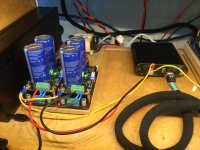
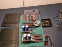
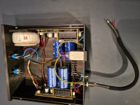
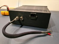
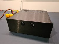
Nice boxed linearpi with UcConditioner
Hi,
I finally got around to building my linearpi and UcConditioner in a nice box.
It is currently switched as 10v output but can be split into 2x 5v. With an extra output connector.
Hi,
I finally got around to building my linearpi and UcConditioner in a nice box.
It is currently switched as 10v output but can be split into 2x 5v. With an extra output connector.
Attachments
-
 98A09CD5-61B1-441C-9EE0-40A2EBE342D0.jpeg269.7 KB · Views: 239
 -
 15357A29-0B56-4CA7-AB1F-1B43DF80DE50.jpeg288.5 KB · Views: 285
 -
 7AAA0060-964A-402C-B9B9-ED54E11D633E.jpeg297.7 KB · Views: 529
 -
 747B2091-74E5-49CB-B504-2D390BE1E31E.jpeg322.2 KB · Views: 531
 -
 D4858E6C-9A7D-4A4D-B335-E43F84BAED3F.jpeg231.3 KB · Views: 538
 -
 C907E26B-380D-4A0C-AF20-95205572E067.jpeg166.4 KB · Views: 537
Hello Stefan, Supersurfer,
Finally you left your nativity scene style constructions behind you.
I think with these kind of caps you need to make something according to safety regulations.
Usually when something goes wrong with high energy density like super/ultracaps or the latest batteries they will get warm..... hot......flames possibly.
So i would go for a circuit that includes something to monitor temperature with a shut down mode.
My grandfather was killed in a fire when my father was a teenager.
I got arrested starting a fire under a balcony with laundry hanging for drying at the age of 9?
My hotel in Bangkok had a big fire when i was outside when i came back, the firemen on my balcony!
In my present house on the back side someone set fire to a chair ion my balcony.
In my present house the small separation filled with spider webs and bird nest between me and my neighbour after the people who repaired the roof with a torch already left,
I dont want the supercaps to be in the next episode.
Greetings, Eduard
Supersurfer that came out quite nice, I was looking at casing my hairball up and was looking at some rectangular aluminum extrusion. I was also wandering about filtering EMI before the transformer and was thinking the power entry modules were not up the load will have to ck them out again. Also I am building a piconditioner and was wandering if I should glue the caps the the circuit board?
Thanks
Bill
Thanks
Bill
Ian, I got one 5v uconditioner going without issue with the linearpi power supplies. With the second, D8 and D5 light up no problem, but D4 and D9 are not coming on after leaving it charging for a while. I've swapped linearpis and it will not charge up on the power supply that worked with the other uconditioners, so I know it's not the power supply.
I tried resoldering the ultracap pins with higher heat but was getting very small sparks so I stopped. As a result, the ultracaps appear to be getting some electricity.
What do you recommend for next steps?
Edit: And just as I typed this, the conditioning lights came on. The first power supply I used (which was a linear pi) must have delivered more current to charge them initially.
[Does anyone know what the power consumption is of the 3.3V connection on the FifoPi Q3?]
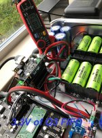
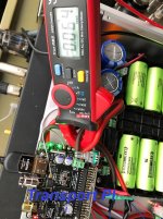
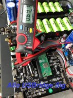
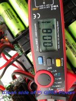
I took some measurements of various parts in my system and attached photos of the results hope that helps.
I took some measurements of various parts in my system and attached photos of the results hope that helps.
Attachments
Hi, could i please get some help working out why my Lifepo4 shuts down after a few seconds.
I ran into a similar problem once if you set your charging point hi like 3.6 and there is no load on J1 and J2 the board will shutdown stating short protection not sure why
Solution Try putting a small load on the 2 x 3.3v
It is also possible your soldering of the batteries or holders did not take well these are very thick copper and need a good heat to soak in test every solder joint with a tester and make sure you did not short anything either
also a puffy cap is not a good thing obviously not sure if you added caps or have wrong polarity on a battery or 2
hope that helps good luck
Does anyone know what the power consumption is of the 3.3V connection on the FifoPi Q3?
There's also this in the manual. But again, pinch of salt as I can easily misinterpret the technicalities.
F. Connector
J5: Clean isolated FiFoPi DC power input
Connect a 3.3V DC / 200mA (minimum) power supply to J5 to power the FiFoPi, MAINTAINING CORRECT POLARITY!!! The FiFoPi consumes about 100mA average current with typical 45.1584/49.1520 MHz XO clocks, a little higher with higher frequency clocks. If you use OCXOs or other high current-consuming clocks, you MUST account for the additional current required in your clocks in your choice of a power supply. We prefer to use a 3.3V ultra capacitor / LifePO4 battery direct power supply.

Last edited:
I did it like this:
Hey @Supersurfer, thanks for this great idea. Evident sonic improvements for my etherregen this evening!
Develop ultra capacitor power supply and LiFePO4 battery power supply
- Home
- Amplifiers
- Power Supplies
- Develop ultra capacitor power supply and LiFePO4 battery power supply