Count me in.
An externally hosted image should be here but it was not working when we last tested it.
Last edited:
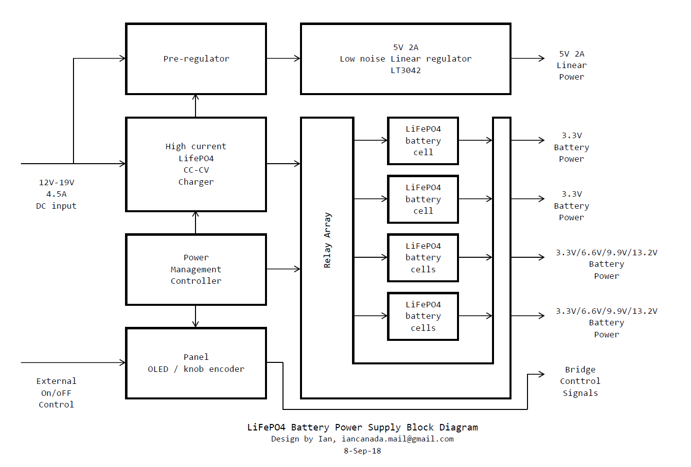
Ian LiFePO4 Power supply block diagram
Ian LiFePO4 Power supply principle block diagram
Voltage rails:
1, Low noise linear regulated 5V 2A: for digital sections (before isolator is suggested);
2, Pure LifePO4 battery power 3.3V: for clock board;
3, Pure LifePO4 battery power 3.3V: for DAC;
4, Pure LifePO4 battery power 3.3V or 6.6V or 9.9V or 13.2V: for I/V stages or analog sections;
5, Pure LifePO4 battery power 3.3V or 6.6V or 9.9V or 13.2V: for I/V stages or analog sections;
All voltage rails are independent from each other.
All battery powered rails are isolated from DC input
Multiple LifePO4 boards can be bridged together for more power rails.
Normal laptop power adapter would be good option as DC input.
LifePO4PowerSupplyBlockDiagram by Ian, on Flickr
Ian
Last edited:
Hi Ian,Ian LiFePO4 Power supply principle block diagram
Voltage rails:
1, Low noise linear regulated 5V 2A: for digital sections (before isolator is suggested);
2, Pure LifePO4 battery power 3.3V: for clock board;
3, Pure LifePO4 battery power 3.3V: for DAC;
4, Pure LifePO4 battery power 3.3V or 6.6V or 9.9V or 13.2V: for I/V stages or analog sections;
5, Pure LifePO4 battery power 3.3V or 6.6V or 9.9V or 13.2V: for I/V stages or analog sections;
All voltage rails are independent from each other.
All battery powered rails are isolated from DC input
Multiple LifePO4 boards can be bridged together for more power rails.
Normal laptop power adapter would be good option as DC input.
LifePO4PowerSupplyBlockDiagram by Ian, on Flickr
Ian
Is not a regulator provided before the chipdac?It is prudent not to foresee it
Last edited:
@sontero
The whole idea is to use LifePO4 battery directly in order to get rid of any LDO/regulator after it.
There is no problem if you DAC runs at 3.3V but with LDO which has 5V input. LDO will be bypassed automatically if the input is lower than the dropout voltage. In this case, you can still feed the 3.3V LifePO4 power into it.
However If your DAC chip runs at 5V originally, you have to use ultra capacitor power supply which will have pure 5V output.
Regards,
Ian
@sontero
I did a lot of test on my ES9018/28/38 DAC HAT with feeding 3.3V directly, I'm very happy with the LifePO4 battery cells.
http://www.diyaudio.com/forums/pc-b...i2s-dac-hats-raspberry-pi-27.html#post5421318
Regards,
Ian
I did a lot of test on my ES9018/28/38 DAC HAT with feeding 3.3V directly, I'm very happy with the LifePO4 battery cells.
http://www.diyaudio.com/forums/pc-b...i2s-dac-hats-raspberry-pi-27.html#post5421318
Regards,
Ian
GOOD !!@sontero
I did a lot of test on my ES9018/28/38 DAC HAT with feeding 3.3V directly, I'm very happy with the LifePO4 battery cells.
http://www.diyaudio.com/forums/pc-b...i2s-dac-hats-raspberry-pi-27.html#post5421318
Regards,
Ian
")
Thanks Ian
I assume that different brands of LifePo4 life capacitors will have different sound Ian ?
This looks very interesting question pls, if we feed the LifePo4 supplies individually to say 5 locations, how is the battery drain being controlled as current consumption will vary.
Thks Ian
This looks very interesting question pls, if we feed the LifePo4 supplies individually to say 5 locations, how is the battery drain being controlled as current consumption will vary.
Thks Ian
@sumotan
It's a very good question.
LifePO4 battery has pretty good power capacity. I have an A123 26650 cell for powering my McDualXO with a pair of OCXO. For years I charge them every 7 to 10 days without having any problem. It would be more than 24 hours for continuous run. The current was around 100mA.
Though LifePo4 battery cells can deliver up to 50A huge current, however, as a kind of chemical battery, any kind of over dis-charge will cause damage to them in some degree, as well as possible damage to the audio gears. So, solutions have to be taken into design consideration:
1. There will be a programmable timer to turn off the LifePO4 battery power supply when time is up, just in case of forgot doing so;
2. An isolated monitoring circuit will be implemented for over dis-charge protection. When dis-charge voltage is lower than the threshold, say 3.15V, the controller will switch it to charging state automatically.
On-board controller will take care of all these kinds of jobs.
BTW, I use A123 26650, I'm very happy with the sound quality.
https://www.batteryspace.com/prod-specs/6610.pdf
Regards,
Ian
@sumotan
It's a very good question.
LifePO4 battery has pretty good power capacity. I have an A123 26650 cell for powering my McDualXO with a pair of OCXO. For years I charge them every 7 to 10 days without having any problem. It would be more than 24 hours for continuous run. The current was around 100mA.
Though LifePo4 battery cells can deliver up to 50A huge current, however, as a kind of chemical battery, any kind of over dis-charge will cause damage to them in some degree, as well as possible damage to the audio gears. So, solutions have to be taken into design consideration:
1. There will be a programmable timer to turn off the LifePO4 battery power supply when time is up, just in case of forgot doing so;
2. An isolated monitoring circuit will be implemented for over dis-charge protection. When dis-charge voltage is lower than the threshold, say 3.15V, the controller will switch it to charging state automatically.
On-board controller will take care of all these kinds of jobs.
BTW, I use A123 26650, I'm very happy with the sound quality.
https://www.batteryspace.com/prod-specs/6610.pdf
Regards,
Ian
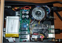
Hi Ian - I am looking forward to your progress on this. Just as a reference, I built a quick and dirty LiPO supply for my Allo isolator and Boss DAC. The Raspberry Pi is powered by a 5 volt linear supply (which also powers the battery charging module). 2 relays are used to switch the LiPOs between parallel for charging and series for powering the isolator. A third relay switches the power out to the isolator between battery and unregulated power, so that the isolator and DAC are totally galvanically isolated from the Pi.
The relays are controlled by a GPIO pin which goes high when the player is active (it is running PiCorePlayer). When the player is quiescent, the batteries are switched into charge mode. This works well enough so that the batteries always have enough charge for extended listening.
This is pretty simplistic, so for my next project, I would like to implement your idea.
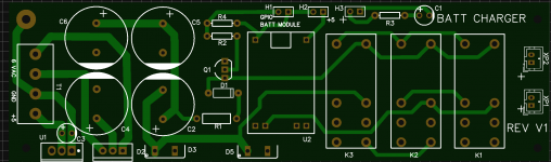
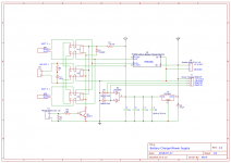
Pictures (one is the custom PCB I made for this) and schematic attached for anyone who wants to duplicate.
Regards
Whit
Attachments
Ian, why not just do Regulator -> LifePO4 -> Super capacitor?
The regulator will keep the battery and the capacitor charged 100% of the time and the battery+capacitor act as low impedance power delivery while also filtering out the remaining noise from the regulator.
The best of all worlds.
I never understood why people want to place a battery or super cap before the regulator.
Last edited:
Ian, why not just do Regulator -> LifePO4 -> Super capacitor?
The regulator will keep the battery and the capacitor charged 100% of the time and the battery+capacitor act as low impedance power delivery while also filtering out the remaining noise from the regulator.
The best of all worlds.
I never understood why people want to place a battery or super cap before the regulator.
Using batteries as a capacitor replacement is easy and gives excellent results. But unlike Ian's project it does not provide a galvanic or noise isolation. Combining batteries with supercaps, otoh...not sure what that achieves.
I'm just curious as to what LifePO4 batteries or super caps add to the equation that regulators don't.
If you slap relays in between them you are going to add a lot of HF inductance between the supply and ground. Plus what little information I could find about LifePO4 and super cap impedance at RF was not very useful.
If you slap relays in between them you are going to add a lot of HF inductance between the supply and ground. Plus what little information I could find about LifePO4 and super cap impedance at RF was not very useful.
Galvanic isolation can still be had. I'm currently using 7.2v Nicad batteries to power the 5V regulator circuits.
Nicads have pretty low power density and limited charge/discharge life cycles. Not sure what the noise factor is, but you should consider lithium chemistry.
Cheers
Whit
- Home
- Amplifiers
- Power Supplies
- Develop ultra capacitor power supply and LiFePO4 battery power supply