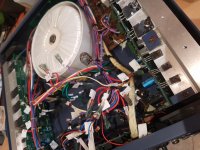
Right so I bought this amp a while ago second hand and something blew reasonably soon after, I had it tucked away until the other day when I decided to do something about it.
Amp is a MilTec MTA 1200 I believe
Power Output:
570+570w RMS/4 ohm
370+370w RMS/8 ohm
Mono/BTL:
1150w RMS/8 ohm
Total Harmon Distortion:
<0.04%
Freq Respon @ 10V.Rms:
10Hz-40KHz/8 ohm
Damping Factor:
>200 8ohm
Slew Rate:
>35v/US
Input Sensitivity(+ - 1dB):
1.4V R.M.S.
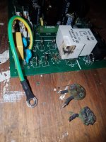
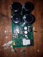
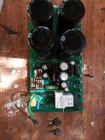
Looking inside it appears that one of the thermistors on the soft-start circuit of the power conditioning circuitboard had blown up, I am assuming and hoping due to old age (the rest of the amp was looking pretty crusty).
Easy enough replacement (also hoping that the adjacent inductor wasn't damaged), however, the markings on the working thermistor (in parallel) have been scorched out. Measuring it at room temperature shows 30 Ohms, the circuitboard underneath says 40R, however, I don't really have any idea of what sort of range I need.
As I understand it the resistance at room temperature should be the highest as to protect the smooth out the current when the amp is switched on, therefore, should I be okay simply replacing them with any other 40 Ohm NTC thermistor provided it can take the current?
Attached are some picture for explanation,
thanks in advance for any help given.
Amp is a MilTec MTA 1200 I believe
Power Output:
570+570w RMS/4 ohm
370+370w RMS/8 ohm
Mono/BTL:
1150w RMS/8 ohm
Total Harmon Distortion:
<0.04%
Freq Respon @ 10V.Rms:
10Hz-40KHz/8 ohm
Damping Factor:
>200 8ohm
Slew Rate:
>35v/US
Input Sensitivity(+ - 1dB):
1.4V R.M.S.
Looking inside it appears that one of the thermistors on the soft-start circuit of the power conditioning circuitboard had blown up, I am assuming and hoping due to old age (the rest of the amp was looking pretty crusty).
Easy enough replacement (also hoping that the adjacent inductor wasn't damaged), however, the markings on the working thermistor (in parallel) have been scorched out. Measuring it at room temperature shows 30 Ohms, the circuitboard underneath says 40R, however, I don't really have any idea of what sort of range I need.
As I understand it the resistance at room temperature should be the highest as to protect the smooth out the current when the amp is switched on, therefore, should I be okay simply replacing them with any other 40 Ohm NTC thermistor provided it can take the current?
Attached are some picture for explanation,
thanks in advance for any help given.
Attachments
It is an NTC, Negative Temperature Coefficient Thermistor.
When cold high resistance and hot low. Just there to allow the power supply to start up then the 'inductor', actually a relay, the relay pulls in across it and shorts the NTC's out.
Probably a fault in the power supply not letting the relay pull in or relay contact not making properly. Check the relay first and place a 100W light bulb across the NTC lands to avoid blowing the new NTCs up.
Thermistor needs to be same diameter and thickness as a first-in part selection, as well as having a 30-40 ohm cold resistance. If the NTC is physically smaller then it may not survive the in-rush energy requirement of the amp.
I'd suggest also putting a light bulb tester on the AC mains input for the first test, in case there is an unforeseen failure. That light bulb may upset normal operation of the relay.
I'd suggest also putting a light bulb tester on the AC mains input for the first test, in case there is an unforeseen failure. That light bulb may upset normal operation of the relay.
Any update on this regarding the thermistor? I am repairing one of these amplifiers now and I too need to find a pair of replacement thermistors that have failed.
I've looked into this component and I have decided that part number SL22 40005 Manufactured by AMETHERM looks as though they would be suitable.
David
I've looked into this component and I have decided that part number SL22 40005 Manufactured by AMETHERM looks as though they would be suitable.
David
To check your NTC resistor type (size and value) you can look some other NTC resistor datasheet (same +- size). This resistors have value of nominal current and full amp current must be lower than this value (multiplied by 2) - it is first condition. (Output power 1150w means that power consumtion from wall socket can be about 2 kVA (or more) - it is about 10 amps or more (for 220 V wall socket voltage).)
Second condition (how you can choose value of NTC nominal resistance) - resistance of cold NTC have to be a little (? or several times) bigger than active resistanse of power transformer primary winding.
Second condition (how you can choose value of NTC nominal resistance) - resistance of cold NTC have to be a little (? or several times) bigger than active resistanse of power transformer primary winding.
Last edited:
- Status
- This old topic is closed. If you want to reopen this topic, contact a moderator using the "Report Post" button.
- Home
- Amplifiers
- Power Supplies
- Soft-Start Circuit Thermistor suggestion