Rod Elliot's analysis* - about the decent only one that can be found - clearly shows that the diodes are there to protect the series coupling electrolytic caps against reverse bias. They have nothing to do with standing-off 'DC' - they do not do that, at all, given the superposition of large AC voltage.
Hence my earlier post #12. DC blockers require large-value capacitance to do ...something; merely using 'more diodes and some film-caps' = no use at all.
* Mains DC and Transformers. Recommended reading.
Hence my earlier post #12. DC blockers require large-value capacitance to do ...something; merely using 'more diodes and some film-caps' = no use at all.
* Mains DC and Transformers. Recommended reading.
Last edited:
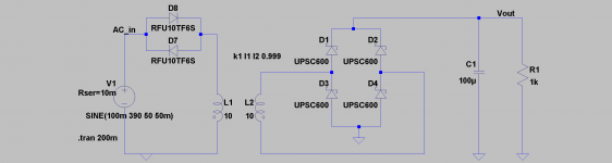
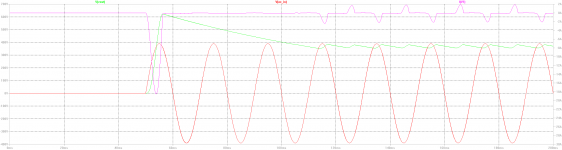
Well LTSpice shows diodes work well as DC block.
I did a very simple ckt, and if just looking at the voltage you can't see a difference, but looking at the current... which toroids do not like.
Here 100mV DC offset, unrealistic 10mohm series resistance, and with diodes shorted, the standing DC current is 10A, that's 100mV/10mohm.
I have only used a DC blocker once, on my main amp with a big toroid. It hummed, DC blocker silenced it. But I didnt notice any benefits sound wise, only less annoying hum, good enough for me... And I intend to try them again, perhaps paying a little more attention to the sound, if I ever try without first.
Edit: I should add that the DC blocker I have built does include large capacitors in parallel. I also think they need to be there, but after the simulation, I begin to wonder if the Primaluna ckt might just be as good.
Attachments
Last edited:
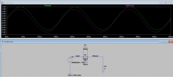
Not Sure... LTSpice tells me diodes don't work in filtering the DC component from AC simply because the DC component on AC is not a steady voltage but an assymetry between positive and negative. Using low voltages to make this visible. The same effects play with higher voltages.Well LTSpice shows diodes work well as DC block.
I did a very simple ckt, and if just looking at the voltage you can't see a difference, but looking at the current...
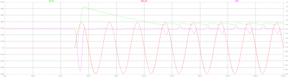
1. Just antiparallel diodes... : 1.5V sine with 200mV offset. The filtered "positive" and "negative" halfs are still assymetric. Relatively there's more assymetry. With a 300V sine, the assymetry will still be there, not as visible though.
2.Add a large enough cap accross:
The DC component is gone:
3. Using a small cap:
Same assymetry as in the first case, but a tiny bit smoother. :
That said, I don't believe Prima Luna or PSaudio would built such things if doesn't reduce humming. I just don't understand why yet... . maybe the few volts the diodes pinch off is enough to reduce core saturation induced humming?
Attachments
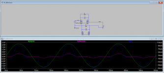
The diodes will block up to their threshold voltage Vf, 0.5-0.6V typical Si diodes, so yes that is lost on the output, noticable on your 1.5V sine. With mains voltage one or two diode drops isnt so critical. You clearly see how they block your DC offset + sine up to Vf.
The few mV the diodes block is enough to make a difference on some transformers. If you have a few V DC offset on your line you need to contact the mains provider.
The few mV the diodes block is enough to make a difference on some transformers. If you have a few V DC offset on your line you need to contact the mains provider.
The power distributor will measure whether the power at your (or my) house meets the standard. Where I live the NBN EN 50160 standard applies. And this standard allows for a 2% imbalance. 2% on 230V is way more than the 200-500mV I measure here (I had a humming amp, called the distribution company, had it measured, and was found to be within spec...) http://www.cdtechnics.be/542-standard-en-50160-voltage-characteristics-in.pdf
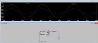
a sine wave with dc looks like a*sin(b)+c, where c is your DC component
with two anti-parallel diodes, and given a>>500mV you get (a-500mV)*sin(b)+c
i.e. your DC component c is still there. the only thing you get is a 500mV lower amplitude and crossover distortion.
This is what I see in LTspice. The bottom half of the AC goes to 0.4V, the top half to 0.6V. The 200mV DC offset is still present... . If it works, something else is at play... .
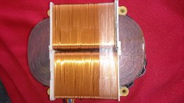
While waiting for some parts to replace in 30 year old mono amps I put together 8 NXP byv29's and two chinese mkp x2's (total 4 euro cost) and tried this Primaluna circuit with one of the mono amps playing through Chromecast audio. Clearly audible punchier better detailed bass and I think also better detailed treble, but bass immediately stood out. Listening to mono, one channel, because other mono amp is in parts") Transformer inside isn't a toroid and wasn't obviously humming either. Will compare on stereo later, but if this is pure psychological I do like this mindtrick.
Transformer inside isn't a toroid and wasn't obviously humming either. Will compare on stereo later, but if this is pure psychological I do like this mindtrick.
Transformer inside isn't a toroid and wasn't obviously humming either. Will compare on stereo later, but if this is pure psychological I do like this mindtrick.Attachments
Yesterday I built the ver2 and installed it in the power strip for my audio equipment. Playing the same Chesky records tracks, these are after effects so far:
- the slight mechanical buzzing noise coming from my amp is gone. The amp is completely silent.
- for the same volume (28 out of 80), it's louder.
- the bass is stronger, more defined
- the soundstage is "clearer"
The most obvious change is the volume.
Very interesting. Looks like dynamics has been increased.
Did you measure the DC offset before and after the circuit? It would be interesting to determine the amount of diodes needed.
The power distributor will measure whether the power at your (or my) house meets the standard. Where I live the NBN EN 50160 standard applies. And this standard allows for a 2% imbalance. 2% on 230V is way more than the 200-500mV I measure here (I had a humming amp, called the distribution company, had it measured, and was found to be within spec...) http://www.cdtechnics.be/542-standard-en-50160-voltage-characteristics-in.pdf
a sine wave with dc looks like a*sin(b)+c, where c is your DC component
with two anti-parallel diodes, and given a>>500mV you get (a-500mV)*sin(b)+c
i.e. your DC component c is still there. the only thing you get is a 500mV lower amplitude and crossover distortion.
This is what I see in LTspice. The bottom half of the AC goes to 0.4V, the top half to 0.6V. The 200mV DC offset is still present... . If it works, something else is at play... .
Yep, you are right. The diodes only cut the base of each half sine wave form. They don't block the DC offset, because the asymmetrey is still there. Even increased.
Perhaps is the added crossover distortion, the resulting harmonics, thath help the toroidal transformer not humming.
I would say that the Nordost QV2 works in a similar way.
QRT | Qv2 AC Line Harmonizer
Yesterday I built the ver2 and installed it in the power strip for my audio equipment. Playing the same Chesky records tracks, these are after effects so far:
- the slight mechanical buzzing noise coming from my amp is gone. The amp is completely silent.
- for the same volume (28 out of 80), it's louder.
- the bass is stronger, more defined
- the soundstage is "clearer"
The most obvious change is the volume.
Would you please try to explain the DC blocker's impact on your amplifier's gain?
Best regards!
Magic And/or confirmation bias (which ultimately adds up to the same thing )...
And/or confirmation bias (which ultimately adds up to the same thing )...Would you please try to explain the DC blocker's impact on your amplifier's gain?
Best regards!
Well. A few days ago I came across with this Emotiva DC Blocker, that seems to follow a similar design, rectifiers plus small capacitors.
How to Fix DC Offset and Transformer Hum In Your Audio Equipment: A Review of the Emotiva CMX-2 AC Line Restoration System - Poor Audiophile
The device is well regarded, and looking at some reviews in Amazon, etc, it seems to work in most cases. And it contiues intriging me why.
I think the answer coul be in this clever post #48 from JohanB
http://www.diyaudio.com/forums/solid-state/279794-toroidal-transformer-noise-5.html#post4455271
Best Regards.
One thing which surprises me in the above circuit is where does all the current passes through? Through the diodes? or the 0.1uF capacitors or the Rsw?
In most of the DC filters I have seen massive capacitors in parallel like 33000uF/10V or so. Im just curious that does that above circuit works as is? how much current was actually drawn through it though.
In most of the DC filters I have seen massive capacitors in parallel like 33000uF/10V or so. Im just curious that does that above circuit works as is? how much current was actually drawn through it though.
check out this thread:
https://www.diyaudio.com/community/...mary-of-the-most-interesting-comments.197849/
https://www.diyaudio.com/community/...mary-of-the-most-interesting-comments.197849/
I've just browsed and am halfway through the thread, so no comment, but I can correct the below, following link:The circuit in the picture appears to be a DC block, and not a very well designed one at that.
Rod Elliott reorganised his website. You can now find that excellent article at:Here's what Rod Elliott recommends:
You can read his writeup here:
https://sound-au.com/articles/xfmr-dc.htm
Now to read the rest...DC on the mains can cause some mains transformers to hum from mechanical vibration. The DC blocker eliminates this hum. It doesn't impact the signal amplified by the amp in any way, it is purely to address any mechanical hum/buzzing of the transformer.
Tom
I remember a book by Memo Vanderveen that had such a circuit in a sort of appendix.
Curing issues is of course nice and DC blockers work OK for humming toroids but what about choosing a transformer that is less sensitive to mains DC components? A second way of dealing with it is to use an isolation transformer. I can not recommend enough what a difference the isolation transformer makes.
Rod Elliot's analysis* - about the decent only one that can be found - clearly shows that the diodes are there to protect the series coupling electrolytic caps against reverse bias. They have nothing to do with standing-off 'DC' - they do not do that, at all, given the superposition of large AC voltage.
Hence my earlier post #12. DC blockers require large-value capacitance to do ...something; merely using 'more diodes and some film-caps' = no use at all.
* Mains DC and Transformers. Recommended reading.
Just to correct that old link again- it's now as below:
Rod Elliott reorganised his website. You can now find that excellent article at:
https://sound-au.com/articles/xfmr-dc.htm
"I remember a book by Memo Vanderveen that had such a circuit in a sort of appendix."
It was in toward the end of this one, the only book of his I've held in my hands, from the local library.
I hope he won't mind if I paste that brief appendix note as relevant to this discussion.
Scanned in two pages.


I hope that's something, a useful contribution perhaps.
Meanwhile, the links above look as though they'll have a lot of reading time.
~ Ross
It was in toward the end of this one, the only book of his I've held in my hands, from the local library.
I hope he won't mind if I paste that brief appendix note as relevant to this discussion.
Scanned in two pages.
I hope that's something, a useful contribution perhaps.
Meanwhile, the links above look as though they'll have a lot of reading time.
~ Ross
I know, isolation transformer (1:0,9) for approximately 215-220VAC is the royal way, but unfortunately very expensive for high power amplifiers, because the necessarily VA value is very large.Curing issues is of course nice and DC blockers work OK for humming toroids but what about choosing a transformer that is less sensitive to mains DC components? A second way of dealing with it is to use an isolation transformer. I can not recommend enough what a difference the isolation transformer makes.
Best choosing for a transformer, that is less sensitive to mains DC components are Plitron
https://www.plitron.com/home.html
and Tauscher (English version don't goes open)
https://www.tauscher-transformatoren.de
check out also this PDF
http://www.dalitech.com/Resources/Measuring Acoustic Noise Emitted by Power Transformers.pdf
While performing various listening tests between Tauscher and the genuine toroidal transformer in an integrated amplifier from Plinius Audio I note follow:
Although the transformer from TAUSCHER no longer had any mechanical humming without a DC filter (compared to the original one with the red hedgehog as the company logo, which ran at idle and loud audibly hummed from approx. 232-235V mains voltage), the DC filter unexpectedly brought additional improvements in terms sound quality.
Obviously DC components on the mains lead to an increase in interference radiation in the amp device, even with high-quality transformers without any perceptible mechanical hum and noise effects.
Please note, that this observed impressions did not take into account the effects described here:
https://www.diyaudio.com/community/threads/rc-snubbers-for-diode-recovery-noise.190638/
https://www.diyaudio.com/community/...rmer-snubber-using-quasimodo-test-jig.243100/
https://www.diyaudio.com/community/threads/standard-silicon-diode-rectifiers-vs-ultra-fast.260165/
https://www.diyaudio.com/community/threads/dipping-resonance-of-some-audio-transformers.341133/
Probably with a right snubber network so as ultra fast (soft recovery) rectifiers additional DC filter don't provide any benefit in order of the sonic character - but this wasn't investigate at those days.
Last edited:
- Home
- Amplifiers
- Power Supplies
- Primaluna's AC Offset Killer