The build looks done correctly. Add solder to M1 & M2 legs on the upper layer too in the end, I see a weird thing around M1's middle leg but it should be a reflection. Maybe the board could also be bit better cleaned underneath if you would nitpick. Nice photos by the way.
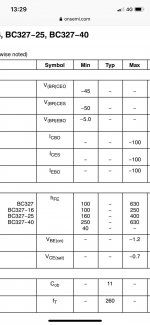
Are those BC327 legit? Their surface is dull and their print looks poor. Not having their -40 higher hfe range suffix even.
The Tx should go bit lower when loaded but its right on the max input spec when not. Maybe not the culprit.
IRF9610 for M1 is an alright choice for up to 1A CCS settings.
Check Jfets are neither shorted between d-s nor showing too high ohms either when the board's off power firstly, then check the Vbe of transistors & Vgs of Mosfets when the board is powered. 0.55-0.65V Vbe & 4-6V Vgs M1 3-4V Vgs M2 should be in range.
The last pictures.
Regards,
Rudy
P.S.
Just one more thing. Check LEDS can be lit with a capable DMM in diode mode or with a >2V battery. No need to remove them from board for that test. Its possible 3mm LEDs can fail right after too hot soldering or to get weak because of that and fail in a month or so.
The leds are burning with the multimeter in diode mode.
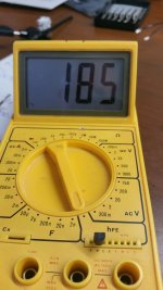
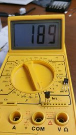
I also messure hfe from the 2 bc 327-40 and this are the results.
It looks these are bc327-16 or bc327-25 types or fake ones, I ordered this ones in The Netherlands.
Regards,
Rudy
I also messure hfe from the 2 bc 327-40 and this are the results.
It looks these are bc327-16 or bc327-25 types or fake ones, I ordered this ones in The Netherlands.
Regards,
Rudy
Attachments
Last edited:
I’m looking to build an UltraBiB 1.3 for my DAC (Simaudio Moon 100D) to replace the 18V switch mode wall wart it came with. I took some measurements of its current use - it draws either 70, 80 or 90mA while in standby/off mode (I’m not sure why, but it draws a different amount each time and remains pretty steady) and up to around 190mA when playing music. The manual states the unit should be left on 24x7 as it will take “several hours” to reach “peak performance” upon power-up.
My questions:
1) With respect to spare current, even if I choose 50mA for playing music (ie. CC = 240mA), I may end up with 170mA spare when the unit is in standby. According to the build guide, I’ll start to see current noise and changes in the characteristics of M2. How much of an effect will I see to the DAC when I then take it out of standby and start playing music? Will the noise decrease after the “on” thermal equilibrium is reached?
2) With 50mA spare current, M2 will have to dissipate a little over 3W of heat during standby, and M1 will dissipate around 1.5W continuously. I’ll be putting the power supply in a Hammond 1455Q2201 chassis, which is 2mm thick aluminum 220x125mm. Is this sufficient sinking? There doesn’t seem to be room on the board for separate heat sinks.
3) If I won’t see any problems from 1) and 2) with 50mA spare current, should I consider 100mA? (CC = 290mA, 220mA spare during standby, M2 dissipates 4W, M1 1.75W)
4) Would Salas’ L-Adapter be more suitable for this application? I’m a little worried dumping so much power with the unit being powered up all day.
1) Its not an optimum standby spare but still not genuinely noisy or unstable. As its also optimum to have 100mA spare when playing music.
2) Its 290mA CC for 100mA optimum and your sink is still sufficient. Yes it will be better biased when playing music.
3) See 1 & 2
4) Yes L-Adapter is far more suitable efficiency wise. Especially for around the clock standby.
2) Its 290mA CC for 100mA optimum and your sink is still sufficient. Yes it will be better biased when playing music.
3) See 1 & 2
4) Yes L-Adapter is far more suitable efficiency wise. Especially for around the clock standby.
")
Why were the "square" LEDs specified?
For 15V can I use 5mm round Red LEDs Vf=
1.94V?
Yes you can use other shapes and makes of reds if they fit.
Those specific brand and type Leds proved more consistent in VF tolerances between samples, that is why specified, not because of shape.
I don't think there was opposite equivalent type to use. If anybody knows of low gate threshold Logic Level P-MOS will be nice. In case of only such N-MOS available, a trick would be to make two positive regs with those and then use them floating with middle point as "zero" like stacking batteries in series. The lower reg in the stack is then seen as "negative".
I don't think there was opposite equivalent type to use. If anybody knows of low gate threshold Logic Level P-MOS will be nice. In case of only such N-MOS available, a trick would be to make two positive regs with those and then use them floating with middle point as "zero" like stacking batteries in series. The lower reg in the stack is then seen as "negative".
Thanks for your prompt reply!
My three boards are + 5V, + 15V, -15V. When I soldered the components on the + 5V board, it was able to output + 5V normally. However, the output of the + 15V and -15V boards are not normal, the lights will not light up, and the high voltage cannot be adjusted. Does anyone know where the problem might be? I suspect one of transistors has burned out.
Here is the list of components I ordered.
844-IRF9530PBF for -15V is less ordered in this list.
Here is the list of components I ordered.
844-IRF9530PBF for -15V is less ordered in this list.
Last edited:

There was no IRF9530 in that order list indeed. What you put in its place?
Anyways, first read up close with a flashlight all the components and confirm they are the correct ones in the right places. The Rf resistors or links in their place must be there too. Else there will be discontinuity.
Make replacements if necessary. When all are correct read voltages Vgs for MOSFETS and Vbe for BJTs.
Lets us know those readings.
I deleted my profile and posted it again. I have purchased 844-IRF9530PBF nearby, but not from Mosuer.
My three boards are + 5V, + 15V, -15V. When I soldered the components on the + 5V board, it was able to output + 5V normally. However, the output of the + 15V and -15V boards are not normal, the lights will not light up, and the high voltage cannot be adjusted. Does anyone know where the problem might be? I suspect one of transistors has burned out.
Here is the list of components I ordered from Mosuer.
View attachment OrderHistory (2) (1).pdf
- Home
- Amplifiers
- Power Supplies
- Salas SSLV1.3 UltraBiB shunt regulator