Ok, I finished my negative board and went to test is using a 22v transformer hooked, to my variac. Brought the power-up slowly while monitoring my DMM
and nothing happens the LEDs don't come there wasn't any smoke or burnt smell. I had 50 volts AC at the input even as I increased the voltage still nothing at the output. I did measure -5vdc at the pad of Cx and 5vdc on the other side. I see other builds have a resistor Rf but I thought you could just leave that out. Any thoughts
Thanks
Dave
You may choose not to use Rf (adds a little RC filtering for EMI) but you must certainly substitute it with a wire link then.
You may choose not to use Rf (adds a little RC filtering for EMI) but you must certainly substitute it with a wire link then.
Thank you Salas
I had the resistor for Rf installed it and test it real quick and everything was working. I post more as soon as I make some more progress.
Regards
Dave
I'm sure 50Volts exceeds the voltage limit. Lucky you didn't have Rf in circuit.
Yes it would have I should have wrote it different the 50 volts was what was at the variac out and transformer primary's the secondaries was 15 Vdc
A question for Salas: I dont see you using a capacitance multiplier in any of your regulator designs, yet a capaitance multiplier is often used in other peoples' designs prior to the regulator. Is there a reason you choose not to use capacitance multipliers? Seems there is potentially a lot to gain in terms of ripple rejection and only a couple of volts headroom to lose. I would appreciate your comments (because I'm considering using one in front of your regulators).
Actually I use the principle in my series PSU designs. ")
DCSTB and L-Adapter have C-Mult as core. They do reduce current by 1+β (Hfe) through the R part of an RC filter with C situated at a transistor's base. Its a CCS but also working like a high R. Although the cap remains the same for RC time constant, effectiveness on ripple gets multiplied. Acting bigger since a given capacitance is to handle much less current than it would if not shielded by the beta.
Because loop feedback from the output to their Vref is not involved I call them stabilizers and not regulators in their build guides. Since input voltage changes are still not followed. They also utilize Sziklai output pair arrangements. Offering well lower & flatter Zo plots than typical C-Mults. The core topology is kinda hidden application-wise by the non typical properties as a whole.
In SSLV shunt types the input CCS is not only a useful limiter but filters also. CCS is a high impedance that nodes with Cout so RC. You may additionally use a capacitance multiplier before an SSLV but I don't recommend it post SSLV because it will mess up its Zo.
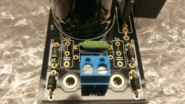
Completed my DAC PSUs. the output stage pulled ~ 100 mA so I sized the +/- 15v boards for 200 mA each. I added some solid 1/4" x 2" x 5 1/2" aluminum as heat sinks for the PSU's, no room to do much else. After 1 hour with lid on they measure ~ 130 F, not cool by any means but a manageable temperature. I used 5K pots and they all adjusted easily to be spot on. Thanks for the great design Salas.
Paul
Paul
Attachments
If its not an application issue like hard limiting and droop due to overloading, check if MOSFETS Vgs is still strong say 3-5V and BC transistors have about 0.6V healthy Vbe.
Nick,
It was a simple and dreaded MOSFET grounding on chassis issue that I have been plagued with before.
So, I'm just getting ready to power a dac with the BiB. I have both negative and positive BiBs. I need 26v (+) and (-) floating. Do I just power it with the positive Reg at 26vdc?
Thanks,
Greg
Hi,
I think I did something stupid.
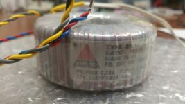
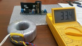
I need 33 volt for my preamp so I use secondary 30 volt transformer, I thought I trimmed it down to 33 or 35 volts.
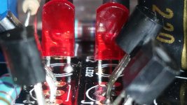
The 2 leds are not burning so I think all the transistors are burnt.
I messure only 5v on the output.
I already ordered new transistors hopefully after I replaced everything it will work.
Edit: I forgot to mention, what is the maximum secondary I can use?
For testing I use a light bulb tester
Regards,
Rudy
I think I did something stupid.
I need 33 volt for my preamp so I use secondary 30 volt transformer, I thought I trimmed it down to 33 or 35 volts.
The 2 leds are not burning so I think all the transistors are burnt.
I messure only 5v on the output.
I already ordered new transistors hopefully after I replaced everything it will work.
Edit: I forgot to mention, what is the maximum secondary I can use?
For testing I use a light bulb tester
Regards,
Rudy
Attachments

Last edited:
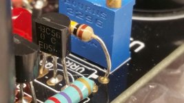
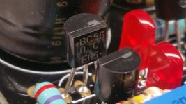
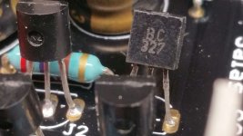
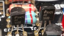
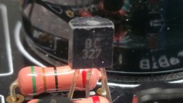
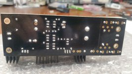
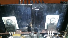
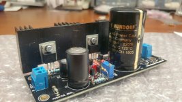
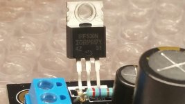
You may use 33VAC max secondary, says so on the schematic notes, maybe its a non related issue. Can use only one secondary because your Tx has 2x30V on the label. When you parallel them first measure what AC they give and that the Tx isn't getting hot, then connect it. See that you have the Rf bridge resistor installed, diodes correctly oriented, no JFETs in place of BJTs, correct MOSFET types to positions, and no shorts from their tabs to the sink.
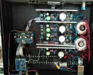
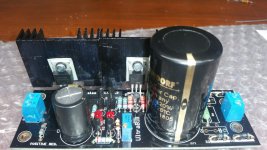
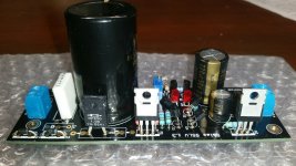
I upload pictures and I see nothing wrong, maybe other people see something I don't see.
I also messure the secondary almost the limit I see...
Regards,
Rudy
I also messure the secondary almost the limit I see...
Regards,
Rudy
Attachments
-
 20191103_130420-1280x720.jpg152.4 KB · Views: 190
 -
 20191103_130344-1280x720.jpg143.6 KB · Views: 171
 -
 20191103_130303-1280x720.jpg155.5 KB · Views: 178
 -
 20191103_130216-1280x720.jpg156.1 KB · Views: 176
 -
 20191103_130122-1280x720.jpg143.6 KB · Views: 178
 -
 20191103_123435-1280x720.jpg216.9 KB · Views: 184
 -
 20191103_123302-1280x720.jpg190.8 KB · Views: 190
 -
 20191103_122412-1280x720.jpg203.9 KB · Views: 391
 -
 20191103_122302-1280x720.jpg249.9 KB · Views: 394
 -
 20191103_122115-1280x720.jpg176.4 KB · Views: 421
Last edited:
- Home
- Amplifiers
- Power Supplies
- Salas SSLV1.3 UltraBiB shunt regulator