Buy the 50VA ones IMO, they are better made and not expensive.
The shunts usually show some of their traits as pre-regulators too so listen first and then modify the negative rail internal arrangements if you feel its a must.
But ask the designer of that preamp circuit if he agrees and on how to do it best with passives or differently.
The grid bias feed (-10V) arrangement should be the main quality consideration I suppose.
Thanks.Will follow your advice.
Nash
A question to Salas: In the PDF you state that C2 is a non critical component, in that it does not affect stability. Yet in the PDF you very carefully recommend Nichicon or Panasonic devices. Why is this if it can be any value from 100uF to 1000uF? Is the noise filtering reliant on a certain uF/ESR specification?
The only electrolytic that is critical from a stability point of view i.e. no oscillations, is the local termination capacitor C3. Can you confirm this?
The only electrolytic that is critical from a stability point of view i.e. no oscillations, is the local termination capacitor C3. Can you confirm this?
C2 is not critical for stability regarding specific ESR. Only C3 is.
C2 is the voltage reference's noise filter capacitor though (an influential part) so I recommend known good quality capacitors for it.
If C2=100uF time of charge to programmed Vout level will be fastest but noise filtering in the VLF region (1/F) will be lightest. In most cases 220-470uF are good compromises. Beyond 1000uF noise filtering shows no serious gains here. There is a chart in post#1 showing the progressive influence of C2's increasing value in very low frequencies noise filtering. A digital clock may appreciate more subsonic noise filtering for instance when a line level linear circuit may not demand it.
The soft start rise time result to target DC output is a combination of course, as it also depends on how high a target Vout is set.

Power Supply
I would like to use Schottky diodes, are these suitable?
STPS2150 STMicroelectronics | Discrete Semiconductor Products | DigiKey
Also would there be a performance advantage if I use CRC instead of the 6,800uF filter cap i.e. 3,300uF + 1R +3,300uF ?
Thanks.
I would like to use Schottky diodes, are these suitable?
STPS2150 STMicroelectronics | Discrete Semiconductor Products | DigiKey
Also would there be a performance advantage if I use CRC instead of the 6,800uF filter cap i.e. 3,300uF + 1R +3,300uF ?
Thanks.
Hello
For what CC current you plan to use those diodes for? They would rectify alright and are efficient for forward voltage drop (VF) but DO-15 is a small package size and you should check they do not overheat. Constant current used in this design puts more burden to the rectification than usual. But if for low CC setting applications not a big deal.
About the CRC instead of C it could be acceptable but use a link instead of Rf in that case. Because as standard its an RC already (Rf+C1).
PSRR and Noise Measurements of Salas regulators are top-notch compared to other regulators. See Post #4147
I have added my name to the demand list. Not in a hurry, so it is OK when closing of the 2nd group buy will take some time.
Thanks to Salas for sharing this design and to Tea-Bag for distribution of PCBs and kits.
I have added my name to the demand list. Not in a hurry, so it is OK when closing of the 2nd group buy will take some time.
Thanks to Salas for sharing this design and to Tea-Bag for distribution of PCBs and kits.
Hi Folks,
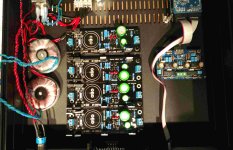
I have a few questions I'm hoping I can get help with. I'm upgrading the PSU to a DAC I have using 2 - 5V and one +/- 15 v Ultra Bibs. The required current draw for one of the 5V psu is ~ 450 mA, the other 5V psu will need to supply ~ 250 mA. The +/- 15v psu will supply the output stage and I don't know the draw since it is not posted with the product specs. To simplify things I'm building each of the psu to supply 600 mA. The real estate in the case is a little tight as you can see in the attached pic. Here are my questions :
1.) Will I need to have heat sinks on M1 & M2 at these current draws ? To do that might require breaking the boards apart to put finned sinks and make it tough to fit everything. I guess I could fab up some aluminum bar sinks to allow the boards to remain unbroken up if required though if the required cooling requirements weren't too high.
2.) To get the +/- 15v psu required for the output stage I was going to join the output grounds of the positive and negative boards to get the -15v - 0v - +15v for the output stage power input. Will this cause any problems ?
Thanks for your help.
Paul
Attachments
The output stage should be using far less mA. Measure it first. With the Ameter in series and some handy +/-15V power source. Maybe 7815 7915 chips if you don't have a lab PSU.
At 5V sections the spare current won't be making high dissipation power on M2s because of the low voltage. Be economical and all sections should be manageable on the chassis as sink. Some thick Alu plate in between helps.
It will be hot enough but there's no space for other plans in your photo.
Set 400mA CC for the 250mA section. Joining zeroes at the load's side is valid too.
A quick question for Salas. I read many times that the positive (or negative) and zero volt wires between regulator board and powered circuit should be a twisted pair. Some argue that is has no benefit in a power supply application. Do you recommend connections are made from the regulator to powered circuit using a twisted pair, or by separate, non-twisted, wires?
They must be saying that on the basis of minimizing loop area i.e. making the interface less of an antenna. About external interference that is because its just DC transfer, it doesn't emit some nuisance field of its own.
In any case just running them wires close together should be good enough. Dressed nicely and held together with a couple of zip ties maybe.
In any case just running them wires close together should be good enough. Dressed nicely and held together with a couple of zip ties maybe.
Ok, I finished my negative board and went to test is using a 22v transformer hooked, to my variac. Brought the power-up slowly while monitoring my DMM
and nothing happens the LEDs don't come there wasn't any smoke or burnt smell. I had 50 volts AC at the input even as I increased the voltage still nothing at the output. I did measure -5vdc at the pad of Cx and 5vdc on the other side. I see other builds have a resistor Rf but I thought you could just leave that out. Any thoughts
Thanks
Dave
- Home
- Amplifiers
- Power Supplies
- Salas SSLV1.3 UltraBiB shunt regulator