I hope any genuine BC337 should be fine or should I look for specific vgs or hfe values?
Just BC337-40, nothing specific.
Just BC337-40, nothing specific.
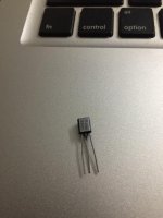
I just found some C550C PH14 series transistors but with silver facing unlike other which are complete black. Not sure whether they are genuine but I just tested and its hFE value is around 495. Can I use this if not I need to buy some BC337 or BC550?
Something like this in the picture.
Thanks
Attachments
Last edited:
Those silver faced are Philips NOS genuine. You can use one for verification until you will get 337-40.
Thanks Salas
")
Just getting started with my spiffy new UltraBiB boards! In the spirit of DIY, I'm going through my inventory of bits and I have a few 10kuF/63V caps. Is there any issue using those for C1? I know the guide calls for 6800uF/50V; I'm running two 24+24 transformers for a dual-mono BA-3 preamp, so the current isn't going anywhere near 1A. I don't think upping C1 to 10k will harm anything, but I'd like the expert confirmation. Thanks!
How much is Q4's Vbe now?
Also how much voltage drop there is between R7's pins?
Between R5's pins?
Voltage drop on R7 is 0.34v, Q4 Vbe is 1v and drop on R5 is 0.10v.
Edit: One more observation, I rechecked and saw that the Q2 Vbe was around 0.32v so replaced with another C550C which had hFE of 485mV. Now I get the max output voltage of -10.11vdc with the replaced Q2 Vbe again being 0.33v.
The voltage drops on R7 and R5 remains the same after replacing the Q2.
All the remaining Qs have the Vbe around 0.58-0.6v except Q2 which has 0.32v and Q4 being 1.0v.
Thanks
Last edited:
Just getting started with my spiffy new UltraBiB boards! In the spirit of DIY, I'm going through my inventory of bits and I have a few 10kuF/63V caps. Is there any issue using those for C1? I know the guide calls for 6800uF/50V; I'm running two 24+24 transformers for a dual-mono BA-3 preamp, so the current isn't going anywhere near 1A. I don't think upping C1 to 10k will harm anything, but I'd like the expert confirmation. Thanks!
Its OK to use a bigger reservoir capacitor when you have it.
Check R5 R6 are the right value. The drop across R5 is also Q2's Vbe and its very little. Replace Q2 Q3 J2 to make sure.
I replaced the Q2,3 with 550C and J2 from my spare positive board kit P5102. Checked R5,6 and they are as per spec 270R. Still the voltage is stuck at -9.9vdc. Below are the readings for your reference.
Vbe across q4 = 1v
Vbe across q2 = 0.34v
Vbe across q3 = 0.51v
Vbe across q1 = 0.56v
Voltage drops on R5 = 0.14v
Voltage drops on R7 = 0.29v
Last edited:
How much is the voltage drop across R1's pins? How much is the raw DC voltage across C1's pins?
You might want to check for cold solder joints for the caps because of the thick copper ground trace. Worthwhile to go through these again.
Thanks guys will check that over the weekend and report back.
How much is the voltage drop across R1's pins? How much is the raw DC voltage across C1's pins?
Just to rule out transformer maybe the issue, I checked today with a 0-23v 0.5A transformer and still the same issue with the output VDC stuck the max at -10.05v.
I checked the C1 pins the voltage drop is 30.05v and the drop on the R1 3.3R 3W resistor is 0.587v.
Thanks
You might want to check for cold solder joints for the caps because of the thick copper ground trace. Worthwhile to go through these again.
Hurray success and thank you so much I rechecked every solder underneath the board and realized that the small Nichicon Muse capacitor one of the leg seemed to be loosely soldered. I reflowed the solder for all the cap legs and success I was able to set the voltage perfectly

My bad I had to replaced most of the active transistors just for the sake of dry solder. I should do the homework again, but as of now running with the replaced C550c transistors and the replaced J2 from another Tea-Bag kit.
Thanks once again.
Now I am getting a weird issue. When I connect the psu via a small junction where I connected the wiring like = +ve, 0, -ve and the 0 here is joined from both the positive and negative boards. After connecting this to the small molex type junction and power up I measured exactly +20,0 and 0,-20v on the above wiring. From the other end of the molex junction when I power connect to the Wayne's line stage which needs +,0,- wiring and power up. The line stage is powered with the LED switching on but the positive psu board LEDs are not lighting and output DC shows 0.05v but the line stage is powered up.
And curiously when I switch off the mains the line stage LEDs goes off and then the positive psu board LED lights up and I get the voltage back and slowly gets switched off in some seconds.
I checked the shortage of the mosfets which look fine but whenever I connect to the line stage which actually is hanging in the air, so not mounted on the cabinet yet because the line stage does not have mounting holes. I have used double sided tape to mount it so that nothing touches the cabinet.
thanks


- Home
- Amplifiers
- Power Supplies
- Salas SSLV1.3 UltraBiB shunt regulator