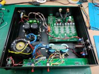
I made a dimensions picture for you guys (also added in post#1)
Salas or Tea, I would really think that making the board count outs as you did on L-adapter would be such a cool upgrade of the layout. Those are very nice idea and would really allow for a smaller footprint of + and - boards if they mounted on the bottom plate of a chassis. Just saying ...
")
Hi Salas!
To build 5volts boards, can I use 25volts capacitors? I have a few nice 25v Kaisei caps. I saw in the guide that C2 and C3 have several values, depending on the brand.
If I use AN Kaisei for these C2 and C3 caps...
can I use 25Volts? Can you please tell me what values (Voltage and μ) you would use with Kaisei?
Here you have the link with those caps Audio Note Kaisei POLAR Low Voltage (16V to 160Vdc) | Hifi Collective
Will 4700μf be enough for C1? Is 6800 or 10 000 really better? Thank you very much for the help.
Last edited:
You can use lower voltage caps in low voltage builds but I don't know if their ESR is OK for C3. Didn't see any technical information in the link.
Higher uF reservoirs keep ripple voltage smaller for higher current loads. Those in BOM were calculated to be ample up to full CC spec. If you are not to use high CC setting and your transfo has headroom, smaller can still be adequate.
Higher uF reservoirs keep ripple voltage smaller for higher current loads. Those in BOM were calculated to be ample up to full CC spec. If you are not to use high CC setting and your transfo has headroom, smaller can still be adequate.
Salas or Tea, I would really think that making the board count outs as you did on L-adapter would be such a cool upgrade of the layout. Those are very nice idea and would really allow for a smaller footprint of + and - boards if they mounted on the bottom plate of a chassis. Just saying ...
Cutouts are not possible in this one because it has to stay physically compatible with BiB 1.1 for plug and play upgrading in already drilled boxes older installations.
Thank you Salas!
What are for you the ideal capacitance of C3 ans C2?
Or, within what range of capacitance should they be?
I am asking this because in the guide there are different options of those caps with very different values and I don't know why is that so.
Thank you.
C2 220uF/50V Nichicon ES or KZ 50-100V If C2 Panasonic FC then 330uF/63V
C3 33uF/50V Nichicon ES or KZ 50-100V If C3 Panasonic FC then 100uF/50V
Ok.
Trying to find R1, when the regulator must feed a 600mA max CC board :
600 = R1 x 700mA (I am giving an extra 100mA for the reg)
So, R1 = 600/700 = 857mOhm
I would use a 3W resistor between 800mOhm and 857mOhm, a very precise one. No compromise here. I noticed that many good 3W resistors are not very accurate at all.
This is more important than boutique caps.
I may use the chassis as a heat dissipator for this.
For the 100mA analogic board, I would add 100mA for the reg, so I have a 200mA CC output demand. No need of big heat sinks. A moderate one will do. Than my fingers will "measure" . Ideally, it shoukd be just a litle bit hot. May be the chassis too, for the long life of those resistors.
Is this correct?
R1 = 600/200 = 3ohm
Ok.
Trying to find R1, when the regulator must feed a 600mA max CC board :
600 = R1 x 700mA (I am giving an extra 100mA for the reg)
So, R1 = 600/700 = 857mOhm
I would use a 3W resistor between 800mOhm and 857mOhm, a very precise one. No compromise here. I noticed that many good 3W resistors are not very accurate at all.
This is more important than boutique caps.
I may use the chassis as a heat dissipator for this.
For the 100mA analogic board, I would add 100mA for the reg, so I have a 200mA CC output demand. No need of big heat sinks. A moderate one will do. Than my fingers will "measure" . Ideally, it shoukd be just a litle bit hot. May be the chassis too, for the long life of those resistors.
Is this correct?
R1 = 600/200 = 3ohm
Use some 50-100 ppm 0.83 Ohm part. Because the voltage across it usually appears bit lower when not exactly 0.6V. Non inductive wire wound types are good there too. See about the lowest and average current consumption of the application so to have enough sinking for M2 and proper R9 value for stability.
Choose a 2.7 Ohm for the 200mA CC application for same near but not exactly 0.6V possibility. If ending up with 210-220mA it does not make any serious change in dissipation. The 600 number in the ballpark calculation comes from 0.6V Vbe. Transistors have tolerances.
PF5102 discontinued by the manufacturer
Hi Salas,
On the Mouser website, the PF5102 transistor is scheduled for obsolescence and is currently out of stock. On the "Product discontinuance notification", there is no recommended replacement.
Although there is still stock at some suppliers, do you have a suggestion of alternative component for the UltraBib 1.3 board ?
Thanks.
So Summing up... for us not engineers.
To feed the SOEKRIS dam1941 ! With A Salas SSLV1.3 UltraBiB shunt regulator
- Shunt Output is 5V and the analogue board needs 100mA :
From 9VAC/30VA to C1 4700μf/25v (or more) , R1 for 200mA is 50 to 100 ppm with 2.7K ohm - R9 has 470ohm and trimmer has 5K for more accurate measuring, (good to adjust from 5 to 15 volts).
- Shunt Output is 5V and the digital board needs 600mA :
From 9VAC/80VA to C1 4700μf/25v (or more), R1 for 750mA is 50 to 100 ppm with 0,83ohm - R9 has 1.5K ohm and trimmer has 5K for more accurate measuring, (good to adjust from 5 to 15 volts).
Sugggestion :
One talema/resin toroid with two 9V/30VA secondaries for analogue 200mA.
One talema/resin toroid with one 9V/80VA secondaries for digital 750mA.
Later, the trimmer can be replaced to make a fixed shunt. But it will be necessary for most people (like me) to set the shunt first with the trimmer soldered. See manual,
VR1 & VRR, last page.
I will use my Kaisei caps on C1 and C2 but in C3 the priority will be low ESR
Last edited:
Hi Salas,
On the Mouser website, the PF5102 transistor is scheduled for obsolescence and is currently out of stock. On the "Product discontinuance notification", there is no recommended replacement.
Although there is still stock at some suppliers, do you have a suggestion of alternative component for the UltraBib 1.3 board ?
Thanks.
Didn't know that, thanks, will have to look into it
Sugggestion :
One talema/resin toroid with two 9V/30VA secondaries for analogue 200mA.
One talema/resin toroid with one 9V/80VA secondaries for digital 750mA.
I think two 30VA/35VA will be fine and on the 750mA transformer it's possible to parallel the secondaries.
All well but mind not 2.7k Ohm but 2.7 Ohm if it wasn't a typo
Oh Yes, thank you!!
I think two 30VA/35VA will be fine and on the 750mA transformer it's possible to parallel the secondaries.
My idea is to have separate transformers for dig and analogue, but if it does not make any difference (because we already have two separate linear psu connected to the shunts), I would use only one. Less space, less money and same performance would be great. What do you think?
In that case I would order a custom Toroidy.
- Home
- Amplifiers
- Power Supplies
- Salas SSLV1.3 UltraBiB shunt regulator