hello Salas,
why not using copper pour on your v1.3 pcb?
are there any disadvantages of using copper pour compared to single traces?
isn't the ground path bigger more better?
thanks.
Not to create further potential return current routes since I was content for noise and stability behavior with those of the test board's bottom ground plane. The return currents naturally try to find the closest path back under the send components routes and this ground plane is largely unbroken by bottom layer lanes, not hindering simple going return paths formation, so I decided to avoid over-complication with the grounding in yet another dimension. I specified thick copper for lower impedance. This level of material also gives some headaches to potential rework with weaker de-soldering techniques is an unfortunate side effect, as the thick continuous ground plane has increased thermal capacity and dissipates spot applied heat fast.
Sharing my experience.
With my system Dam1021 / Raspberry 2B / Salas SSLV1.3 in full operation for weeks, I was quite happy with the result, but I came across the same problem reported by several forum members ... the Salas SSLV1.3 that feeds raspberry It kept very hot and could not close the box with risk to underheat.
My system:
Sedlbauer RSO-825007 2x 0-9v (Raspberry Pi 2B)
Sedlbauer RSO-825008 2x 0-12v (SSLV1.3 Rooms)
1. Salas SSLV1.3 5V (R1 0,57 2W; R9 1K)
2. Salas SSLV1.3 +/- 12V
Raspberry Pi 2B
Dam 1021
He had tried replacing Raspberry PI 2B with Raspberry PI 3 B but did trn on (apparently Raspberry PI 3B requires more current).
As a matter of space, I bought a new transformer, a Noratel TI083474 AU, that I do not know the specifications, except the outputs: 9.6v-0-9,6v; 12v-0-12v; 13.6v-0-13.6v.
After replacing Sedlbauer with Noratel ... to my surprise ...
I was able to connect to Raspberry 3B, with the same configuration as the previous BIB (which did not work!) ...
No heating checked on BIB 5V so far ....
How can I explain? Must you explain?
My project
The first thing Salas is to thank you for this great project that you have shared with us ") .
.
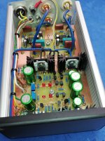
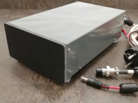
I also wanted to show you some pictures of how I did it.
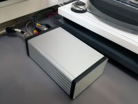
The purpose of the power supply is to feed a preamplifier with RIAA correction for a turntable.I have not used the original PCB and I have designed a custom for the box and that also contains the preamplifier.
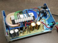
The transformers and rectifiers I have mounted in another separate box and physically separated from the one that contains the preamplifier. I also include the turntable motor power supply.
Any criticism or observation will be welcomed
. I also wanted to show you some pictures of how I did it.
The purpose of the power supply is to feed a preamplifier with RIAA correction for a turntable.I have not used the original PCB and I have designed a custom for the box and that also contains the preamplifier.
The transformers and rectifiers I have mounted in another separate box and physically separated from the one that contains the preamplifier. I also include the turntable motor power supply.
Any criticism or observation will be welcomed
Attachments
After replacing Sedlbauer with Noratel ... to my surprise ...
I was able to connect to Raspberry 3B, with the same configuration as the previous BIB (which did not work!) ...
No heating checked on BIB 5V so far ....
How can I explain? Must you explain?
For bridge rectification the AC current output rating of a transformer must be de-rated at about -40%. Maybe your new transformer has the edge in current output over the previous one and that shows upon the boot.
When the rectification and reservoir capacitor part of the 1.3 starts it has an inrush current peak. All together with the boot momentum of the RPI3B maybe left the previous transfo bit breathless (?)
Thanks Salas.Fully handmade DIY is always nice to see. Does it work well as a whole without noises and giving a good sound? If yes, its a success.
This RIAA preamplifier is connected to an 80 + 80W Exposure amplifier. It does not have the slightest hum.
Only at the top of the volume is heard a shhhh that is appreciated by bringing the ear to the speakers. I attribute it to the opamps that I use, an OPA2134.
It's possible?.
As for the sound, it seems extraordinary to me, but I do not have to compare it
Hiss noise level to stay satisfactory low when with the 8nVrtHz JFET input OPA2134 depends on a. Phono gain to be moderate b. Cartridge impedance to be high c. Total system voltage gain to be moderate d. Speakers sensitivity to be moderate
a & b are pointing to MM cartridge type is better for use with that chip.
So yes, that little hiss is due to the chip. In your case very well controlled while no other noises like hum & buzz are present.
Actually you could afford to test with even worse nVrtHz spec chips, since based on your description, there should be not much detectable hiss at the listening seat on any sane volume control position. AD823 is a direct substitution that I would recommend for a different taste of sound vs OPA2134.
Between those two usually contrasting types of presentations see which one you prefer.
Lower noise JFET input op-amps than the 2134 are not many and usually single type. Like the famous OPA627 if you like the Texas (BB) school. Less expensive is ADA4627 which is roughly analogous. When a circuit has been designed with a JFET input opamp in mind don't substitute with bipolar types.
Hi, check Q2, Q3 Vbe. If not about 0.6V replace.
Q2 and Q3 replaced and everything works like charm.
Thanks Salas!
you are using ultra BIB to power supply op amps and analogue power supplys for AK4497?
and for digital part - Reflecor D as pre regulator?
Yes exactly.
Hiss noise level to stay satisfactory low when with the 8nVrtHz JFET input OPA2134 depends on a. Phono gain to be moderate b. Cartridge impedance to be high c. Total system voltage gain to be moderate d. Speakers sensitivity to be moderate
a & b are pointing to MM cartridge type is better for use with that chip.
So yes, that little hiss is due to the chip. In your case very well controlled while no other noises like hum & buzz are present.
Actually you could afford to test with even worse nVrtHz spec chips, since based on your description, there should be not much detectable hiss at the listening seat on any sane volume control position. AD823 is a direct substitution that I would recommend for a different taste of sound vs OPA2134.
Between those two usually contrasting types of presentations see which one you prefer.
Lower noise JFET input op-amps than the 2134 are not many and usually single type. Like the famous OPA627 if you like the Texas (BB) school. Less expensive is ADA4627 which is roughly analogous. When a circuit has been designed with a JFET input opamp in mind don't substitute with bipolar types.
I thank you again for your attention and your advice Salas.
My theoretical knowledge, are not comparable to yours, but I am glad to have been successful in the diagnosis of noise in my preamp.
The solution of replacing the opamp with an AD823, is cheap and I will be able to use it to see the difference in sound.
Now that I write about this topic and, apologize for my complete ignorance, I wanted to ask you for an opinion about the devices that I have found browsing the Internet: "Audio Discrete Dual Op Amp HiFi Operational Amplifiers OP-AMP replace NE5532". Like the ones you can see at this address:
Audio Discrete Dual Op Amp HiFi Operational Amplifiers OP-AMP replace NE5532 358962406201 | eBay
Could it be a solution? Is it worth the change?
Thanks for your time
Its still 8-13 times higher for input bias current spec than OPA2134 or AD823 (Typical data) plus I don't see you have the space to fit it. Anyways, since this is not the analog source forum and before we go far OT (out of topic) pm me with information about the schematic so I can form a better opinion regarding chips replacement advice.
Yes exactly.
thank you for reply
Is there a problem when you supply digital using only Reflector D or LT3045, I like to know what Is benefit of doubling efforts using both simultaniously
did you try to power digital with Ultra BIB 1.3
I am planning a dual chassis pre-amp / DAC / streamer for which I need multiple power supplies.
One chassis for the (raw) power supplies and the other for above equipment.
Of course it is best to keep the final voltage regulators as close to the circuits as possible.
Is there any reason not to split the UltraBib into 2 sections ?
Up to M1 in the power supply chassis and the rest after M1 in the other chassis ?
Yep, don't break the circuit apart from its main CCS because its fast and we can't predict possible side effects. C1 must be there too else the circuit will oscillate with the incoming cable inductance. But it can have lower value when its not the main reservoir capacitor anymore.
See for your transformer on your mains high side tolerance not to ever bring close to 25V DC rectified in that case. Although 35V caps aren't that much bigger or expensive and usually have less ESR than 25V ones. C3 especially must fall in the recommended ESR range noted on the schematics.
Lower value VR1 will cover lower voltage range applications with more resolution of course. The guide says "10k for 5-25V, 5k for 5-15V".
Lower value VR1 will cover lower voltage range applications with more resolution of course. The guide says "10k for 5-25V, 5k for 5-15V".
Digital sections has two 3.3V inputs and one 1.8v. I decided to use three local lt3045 powered by one reflector @ 5v. One could try to power all digital straight from reflector running @ 3.3v.thank you for reply
Is there a problem when you supply digital using only Reflector D or LT3045, I like to know what Is benefit of doubling efforts using both simultaniously
did you try to power digital with Ultra BIB 1.3
I did not try using bib 1.3 for powering digital, because I do not have additional one
nor I think it can go as low as that (3.3v). Eg. With previous bib 1.1 I could only go to 3.8v the lowest.- Home
- Amplifiers
- Power Supplies
- Salas SSLV1.3 UltraBiB shunt regulator