Has anyone successfully built a +5V 2.2A version suitable for an RPi?
I have put one together using R1 with 0R27 7W, M1 IRF9640, M2 IRF640 and R9 with 1K5. It seems to work but M1, M2 and the rectifier diodes get very hot very quickly, and I seem to have smoked Rf (0R33 1W part supplied in the mini kit).
Should I have uprated Rf?
Also, what is the acceptable heat range for M1, M2 and the diodes? The spec sheet seems to say 150C but this seems quite high.
Any thoughts?
0.33R*2.2A=0.726V*2.2A=1.6W so Rf at 1W rightly smoked. Use a wire link instead of Rf or a 5W one. The bridge diodes need sinking help as they will be dissipating about 2W each.
IRF9640 IRF640 are not tested in this reg before and I don't know what stability margin they may achieve or not. They should at least present a flat DC line without specific waveforms riding at some high frequency as the scope is AC coupled to a probe while scanning with the horizontal knob through various time bases and the vertical knob is set in mostly mV ranges. If so, acceptable.
The quoted max C in semiconductors is core meltdown. Core is always hotter than tab or the plastic shell. Keep the tab below 100C in experiments. To make thermal calculations pay attention to the RθJC term and its listed value. Do a search, many thermal guides for sinking are floating on the web. This old Dave Jones video about thermal heatsink design will give an idea about the concept: YouTube
M2 power at 5V should be low quite low, M1 depends on input voltage, let's say 12V: 7V drop *2.2=more than 15W! For a heatsink temp rise of 20°C above room temp you need something like that: SK58-100-SA | Heatsink, 1.3K/W, 100 x 150 x 27mm | RS Components. You want your UltraBiB reliable so you want good heatsink as other parts can't stand (think caps) the heat. Tiny heatsink on rectifiers' package are cheap.
I hope I'm right else I may fry next build!
Generally correct, 5V only helps, but the RPi is a computer and it will be at many times absorbing just 400mA or below but fully peaking only during boot or when too much USB power is used for external stuff. So M2 will have a wide range of possible dissipation states.
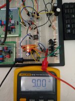
By the way, these days I was bread-boarding a possible linear solution for replacing SMPS bricks to such devices but without the high idling shunt heat. Based on the DCSTB series PSU of DCG3 fame but with a row of pins to can short and select how many Leds are lit for different voltage levels. Will 5V and 9V be enough or someone would need more levels up to near 18V? I don't know, for DACs with external bricks or Class D small amps maybe?
A TO-220 series transistor on a 50mm tall 25.4mm pitch board level sink would handle up to 5A peaks but the sink will be receiving low heat on average say 1.5W at 500-600mA Rpi consumption levels.
A TO-220 series transistor on a 50mm tall 25.4mm pitch board level sink would handle up to 5A peaks but the sink will be receiving low heat on average say 1.5W at 500-600mA Rpi consumption levels.
Thanks for opinion. If I used a ten Leds bar, only five of those are enough for 9V. So another five remain to reach up to 18V. A 2.54mm (0.1inch) pitch dual pins row next to the bar could be accepting a shorting plug to stop the lit Leds count at several voltage levels. Up to 15V eight energized reds are needed. Key for minimal sink saturation is to select a transformer that will not create much in-out DC drop for a given output level goal (2.5V drop is enough for this because BJT series type).
Attachments
By the way, these days I was bread-boarding a possible linear solution for replacing SMPS bricks to such devices but without the high idling shunt heat. Based on the DCSTB series PSU of DCG3 fame but with a row of pins to can short and select how many Leds are lit for different voltage levels. Will 5V and 9V be enough or someone would need more levels up to near 18V? I don't know, for DACs with external bricks or Class D small amps maybe?
A TO-220 series transistor on a 50mm tall 25.4mm pitch board level sink would handle up to 5A peaks but the sink will be receiving low heat on average say 1.5W at 500-600mA Rpi consumption levels.
Yes, up to 18V, please. Even one that could do positive and negative on the same board

So I could use it on, for example, a Soekris DAM1121 - which requires plus and minus 5VDC. After all, it’d be a Salas supply!!
The consumer Soekris units, 1321, 1541 etc are powered by Meanwell SMPS modules. The new 1921 and 1941 require an outboard supply...
I think you’re on to a good thing here, Salas - the ability to substitute factory SMPS supplies with a well-engineered linear supply that can be field altered to different supply voltages to power various devices (for example a NAS) has great potential. Go for it. But make it as universal as you can.
Also, again for example, the Allo Katana has a plus and minus requirement. They’re working on their own linear wallwart replacement to power the Katana.
A ‘universal’ Salas supply to replace SMPS wallwarts seems to me to have great appeal. Even if the implementation was somewhat compromised compared to the UBIB to achieve its universal appeal and price point.
Assuming the price was reasonable, I would jump at replacing the SMPS supplies on my modem, router, NAS etc (all in my audio chain) with a Salas-engineered linear solution that gets as close as possible to ‘one size fits all’. If it could be done such that all one had to do was set jumpers and source an adequately sized trafo the DIY world would thank you
Great concept, sir! Look forward to its realization
ok how much is the role of PF5102 in terms of sound quality improvement? I agree that they are CCS but still there would be difference when moved from 2sk170 to PF5102sI had tried with lab test leads and it was stable. Those were 50cm long.
2SK170 has much transconductance and much capacitance thus it would change frequency parameters in the reg so it owes to have a subjective impact too. Certainly moving it somewhat away from its expected signature. But the PF5102 was chosen as a balanced type for noise gm and pF which is most and above all not NOS. Because the situation with the proliferation of fake expensive Toshiba offers had already moved beyond the farce limit in recent years.
As the beloved SSLV1.1 BiB shunt reg was getting long in the tooth especially for NOS JFETS I had in mind for some time now to design its successor. The goals were: 1. In production parts 2. Much simpler to set up. 3. Better technical and subjective performance.
After many breadboard experiments and two prototype PCB iterations I feel that my goals were finally met. So here comes the UltraBiB
-Uses no NOS parts.
-Can do 5V to 40V output without changing a thing in its parts configuration.
-Nothing to choose and match. No tolerances in predicting its CCS limit setting.
-Has 45dB more open loop gain and many times less output impedance than 1.1
-Sounds easily better.
-Its an electrically and mechanically drop in replacement for an upgrade.
I have already given spare earlier proto boards with now deleted experimental features to few local beta testers. They are all happy by now as far as I know. The pictured board in green is the final layout in just cheapo proto that's a pain to rework and its pads vaporize in the end. It will come in proper grade black solder mask and immersion gold three sections board just like the original.
Attached: Zout plot for 150ma spare current and noise plots for 100,150,220,330,470,1000uF C2 (red 220uF). Also the rails probed on the scope for positive and negative sections. Here are typical values schematics also. I will write a PDF with instructions. Not that there is something truly special to consider when building it with the suggested parts but to describe it better as an item and to clarify details and precautions.
Updates:
31/5/18 R9's value update
1/6/18 OL sim at 100mA spare
2/6/18 Build Guide PDF added (0V0b)
could it be okay to power a 70Vcc input and driver section and, separately, the same final 60VDC power section of a final amplifier?
Clear, revised for the different loads it must feed
By the way, these days I was bread-boarding a possible linear solution for replacing SMPS bricks to such devices but without the high idling shunt heat. Based on the DCSTB series PSU of DCG3 fame but with a row of pins to can short and select how many Leds are lit for different voltage levels. Will 5V and 9V be enough or someone would need more levels up to near 18V? I don't know, for DACs with external bricks or Class D small amps maybe?
A TO-220 series transistor on a 50mm tall 25.4mm pitch board level sink would handle up to 5A peaks but the sink will be receiving low heat on average say 1.5W at 500-600mA Rpi consumption levels.
I suggest following SOtM's lead in this
Though adding 24V to the mix might be a good idea...DC power output
High level output
Voltage : 18Vdc, 19Vdc, 20Vdc, 21Vdc selectable
Current : 4A max
Mid level output
Voltage : 9Vdc, 10Vdc, 11Vdc, 12Vdc selectable
Current : 2A max
Low level output
Voltage : 5Vdc, 5.5Vdc, 6Vdc, 7Vdc selectable
Current : 1A max
and...
does this mean the updated phono pre-amp is on hold?
Too many fixed selections in that list for it when it can simply jump one led reference at a time.
5V 9V 15V 18V are likely and best extra I can do is to put a trimmer also for 2.5V range of additional influence.
The phono update I have figured it out. Will go into its practical things after I finish a current project.
5V 9V 15V 18V are likely and best extra I can do is to put a trimmer also for 2.5V range of additional influence.
The phono update I have figured it out. Will go into its practical things after I finish a current project.
Too many fixed selections in that list for it when it can simply jump one led reference at a time.
5V 9V 15V 18V are likely and best extra I can do is to put a trimmer also for 2.5V range of additional influence.
The phono update I have figured it out. Will go into its practical things after I finish a current project.
The most requests I get is for 5V > 2A up to 12v > 2A. But mostly low voltage gear with greater current, positivr rail.
- Home
- Amplifiers
- Power Supplies
- Salas SSLV1.3 UltraBiB shunt regulator